The RIAA phonopreamp T15B on subminiature tubes. KIT
I want to show you a set of phonopreamp T15B on miniature tubes.
Tubes is used 6Zh1B

Datasheet on this tube

The kit is assembled on three PCB
PCB connectors:

Preаmplifier PCB:

Power supply PCB

Case, two separate compartments. Front and back view.


Photo of amplifier PCB after Assembly

High-precision capacitors and adjustable resistors are used to form the RIAA curve.

Photo of the upper compartment with the amplifier PCB installed.

Photos of the back of the phonopreamp. View of the connectors

Top view of the phonopreamp.

View of the phonopreamp from above in a dark room.

Designed to work with MM cartridges
I want to show you a set of phonopreamp T15B on miniature tubes.
Tubes is used 6Zh1B
Datasheet on this tube
The kit is assembled on three PCB
PCB connectors:
Preаmplifier PCB:
Power supply PCB
Case, two separate compartments. Front and back view.
Photo of amplifier PCB after Assembly
High-precision capacitors and adjustable resistors are used to form the RIAA curve.
Photo of the upper compartment with the amplifier PCB installed.
Photos of the back of the phonopreamp. View of the connectors
Top view of the phonopreamp.
View of the phonopreamp from above in a dark room.
Designed to work with MM cartridges
Last edited:

http://margo.student.utwente.nl/el/tubes/schema/preamp/fb-e180f.gif
Kind regards , Alexander .
P.S.: Ups , not the same , only in the feedback circuit , sorry .
Kind regards , Alexander .
P.S.: Ups , not the same , only in the feedback circuit , sorry .
Last edited:
Yes, this is quite another principle that e.g. has been used by Philips in their AG9015 amplifier: http://www.mif.pg.gda.pl/homepages/frank/instruments/Philips/AG9015/AG9015.pdf
Best regards!
Best regards!
http://margo.student.utwente.nl/el/tubes/schema/preamp/fb-e180f.gif
http://www.mif.pg.gda.pl/homepages/f...015/AG9015.pdf
These are NFB circuits.
What Zampotech has posted is NOT a NFB scheme, but passive EQ.
It IS possible to "overload the input". But like any decently designed amplifier, the output will be insanely large before the input strains.
The "objection" to this plan is that gain depends on tube Gm, and stereo balance depends on tube Gm matching. In commercial production we would like it plug-and-play, no tube matching. In DIY, hand-matching may be part of the fun.
in general, you are right, but this does not apply to cases where the needle catridge gets a scratch or a speck of dust on the vinyl.
then the high amplitude of the signal can cause paralysis of the entire amplifier.
to cause paralysis of this amplifier, it is necessary that the amplitude at the input is greater than 0.2 V at a frequency of 20 Hz, 1.0 V at a frequency of 1 kHz, and 1.2 v at a frequency of 20 kHz.
in the usual case, the amplifier is paralyzed at an amplitude of 0.2 volts at any frequency.
in the amplifier with feedback after paralysis, there is still a post-paralysis syndrome, one single overload outputs the feedback in a nonlinear mode.
for commercial designs, the "manufactured-sold" principle is probably more important, with minimal adjustment costs. There is no doubt about it.
Last edited:
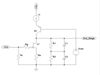
transistor VT1 does not participate in the shaping of the RIAA curve. It provides power to the G2 grid
without this transistor there is feedback at low frequencies.
the idea of this scheme is that a controlled current generator ( pentode) operates on a frequency-dependent load.
in the application of the current generator transistor in the anode load I get mad enhancement in a very narrow operating range of the tube. The circuit will be unstable.
the gain of the cascade will be around 2000, but the operation of the cascade will be similar to the operation of the Schmitt trigger.
Last edited:
As said before, I like your approach! I have another question, though: As pentodes are more prone to noise than triodes, did you measure, simulate or even guesstimate the noise figures of your design? And another one: Do you think these subminiatures are available in the western world also? I must admit that I haven't had a search yet  .
.
Best regards!
.Best regards!
a little later I will show the noise waveform at the output of the amplifier. The noise is slightly above the triode cascade, but slightly.
subminiature tubes are still widely available on eBay.
https://www.ebay.com/sch/i.html?_from=R40&_trksid=m570.l1313&_nkw=5702+tube&_sacat=0
https://www.ebay.com/sch/i.html?_fr...sc=0&_osacat=0&_odkw=6148+tube&LH_TitleDesc=0
https://www.ebay.com/sch/i.html?_fr...&_osacat=0&_odkw=CK605CX++tube&LH_TitleDesc=0
- Status
- This old topic is closed. If you want to reopen this topic, contact a moderator using the "Report Post" button.
- Home
- Source & Line
- Analogue Source
- The RIAA phonopreamp T15B on miniature tubes. KIT