Looks I got it back to front from juggling different windows on screen trying figure the voltages out... sorry.
What you measure is 100% correct, 5 volts on R17 giving zero tuning volts.
A scope would tell us much about what is going on although I suppose the LM7000N is a possibility, much much more so than the big microprocessor. I wouldn't like to guess tbh.
What you measure is 100% correct, 5 volts on R17 giving zero tuning volts.
A scope would tell us much about what is going on although I suppose the LM7000N is a possibility, much much more so than the big microprocessor. I wouldn't like to guess tbh.
I have replaced a couple LM7000N over the years, but this is rare. Microcontrollers almost never go defective except in mains power and lightning events. But then there would be so much other destruction that the uP is a moot point.
I would try one test. Yank the coupling capacitor leading to the LO input and jump it with another ceramic capacitor approximately the same value (not critical at all). See if it starts working. This is a low cost test that you should be able to try without too much trouble.
Keep your eyes open for a good oscilloscope. A used dual trace of 100 MHz isn't that expensive to buy these days. Buy a good brand. These can be had for $200 ~ $250 here in Canada with better 'scopes costing more. This is an instrument that you will use as much as your voltmeter. You will wonder how you ever got by without one. I'm not kidding. At some point later on you might grab a better DVM, preferably a bench meter style. The two most oft used instruments would be an oscilloscope and DVM. These are the basic needs for working on electronics.
So, just keep your eyes open for an opportunity and be ready to pounce on one when it comes available. If the 'scope runs reliably, don't sit there to make up your mind - snag it! If it comes with original probes, make sure you get them. Good probes are very expensive and are much better than the cheap ones on Ebay. The oscilloscopes I would be thinking of are Hitachi, Philips, Tektronix, HP / Agilent, Advance. You can buy a USB type later on after you get a 'scope that tells the truth. Of these, Tektronix has the fattest trace. The others are finer, especially the Philips. Stay away from the Philips Combi-scopes as they do have some overheating issues. I do use a PM3365A on the bench along with an Agilent 54642A (digital). I also have a Tektronix 2465B CT which I find less useful due to it's fat traces. The 2467 has a special tube to give the finer traces most 'scopes have.
-Chris
......Keep your eyes open for a good oscilloscope. A used dual trace of 100 MHz isn't that expensive to buy these days. Buy a good brand. These can be had for $200 ~ $250 here in Canada with better 'scopes costing more. This is an instrument that you will use as much as your voltmeter. You will wonder how you ever got by without one. I'm not kidding.......
Never a truer word spoken.
I always used to say 'no scope, no fixxy' to work colleagues and would use one in preference to a DVM for checking many DC voltages. Noisy supplies, noisy data lines, its all revealed and laid bare.
A good old fashioned analogue 'scope takes a lot of beating as a fault finding tool.
Chris, thanks for the advice on the oscilloscope. I have not used one for an awful long time- back when I was at university as I recall. I take it the coupling capacitor is inside the am/fm front end as I can't see one external to that on the schematic. Looking at the schematic for the front end, I can't easily ID the cap in question. Assuming it must be either be C13 on F-out or C26 on VCC. Bear in mind that the TX540 may differ from the TX550 in that the fm antenna on the 540 goes in to front end box but maybe not the case on the 550. Glenn
Hi Glenn,
Normally there is a capacitor right at the chip for the LO input. But you're right, they may be depending on the one inside the tuner pak. It may just as easily be a cracked solder joint. But, if you have to go into the tuner pack to get at it, don't. It's easy to create other problems. I think you should wait until you have access to an oscilloscope. Do you have a friend that has one? You could drop by with the tuner and have him assist you in looking for things. Then you would owe him a beer.
-Chris
Hi Chris, point taken. No urgency, I have several other vintage tuners which all work fine, some analog, some varicap type. The Yamaha came from the local recycling shop and did not cost much. It served me well over the last few years. I like to tinker and fix things so it was a good project. Some of your Canadian beer is pretty good. I am an Aussie but used to live in Montana and Michigan where Canadian beer like Labatts and Molson was easy to source. Thanks again. Glenn
Hi anatech, Mooley, time to resurrect this thread as I have acquired an analog oscilloscope, Philips PM3070. Came at a good price with one original probe. It seems to work fine but may be very slightly out of calibration judging by calibration signal. Just coming up to speed on how to use it. Should be ready to tackle the tuner again in week or so but will need some guidance on applying the scope to the problem. Hope you will able to assist. Glenn
The Phirips ") D) is quite a complex 'scope so you do need to familiarise yourself with it. When I mentioned 'analogue scope' I was thinking more of an old fashioned type with good old fashioned knobs on it.
D) is quite a complex 'scope so you do need to familiarise yourself with it. When I mentioned 'analogue scope' I was thinking more of an old fashioned type with good old fashioned knobs on it.
I've just had to quickly skim through the thread to see what it was all about... four months is over a thousand posts back for me
So we are looking at the PWM signal from the LM7000 which we think is missing and also the inputs to the chip as a starting point. Have a read back over all that Chris and myself suggested and see whether the scope shows any obvious signs of things missing or things that look corrupted.
D) is quite a complex 'scope so you do need to familiarise yourself with it. When I mentioned 'analogue scope' I was thinking more of an old fashioned type with good old fashioned knobs on it.I've just had to quickly skim through the thread to see what it was all about... four months is over a thousand posts back for me
So we are looking at the PWM signal from the LM7000 which we think is missing and also the inputs to the chip as a starting point. Have a read back over all that Chris and myself suggested and see whether the scope shows any obvious signs of things missing or things that look corrupted.
Hi Glenn,
I'm afraid I might have some bad news about your 'scope. You need to test it to see if my experience holds true for you. It is a very good oscilloscope and while pretty different it isn't that hard to use. I bought one 27 years ago, rebuilt it once and still can use it. I like the scope beyond one fault it causes. I think there is a modification available that will allow it to remember your settings for the next time you spark it up. That would have been handy for me back then.
So, what I discovered is that when you are using that scope, you aren't listening, much less aligning, any FM tuners. The scope interferes with the operation of tuners, so it must be putting out a mash of frequencies around 10.7 MHz, or maybe it's messing up the FM band. I tried using a PM3365 and it had the same problems. Otherwise, a beautiful trace, sharp and clean. Perfect for doing CD players and everything other than FM tuners. I hope your experience is different.
Having said that, it will not interfere with you checking control signals or the local oscillator. Only a received signal is affected.
Do as Mooly recommended and read back over the troubleshooting points we were talking about.
-Chris
Remember that for checking the high frequency high impedance stuff you really need to use a divider probe (a divide by 10 type) which reduces the capacitive loading as seen at the probe tip.
Use the 'Cal' output of the scope to calibrate the adjustable trimmer cap on the probe setting it for no under or overshoot on the Cal squarewave output.
Use the 'Cal' output of the scope to calibrate the adjustable trimmer cap on the probe setting it for no under or overshoot on the Cal squarewave output.
Hi Glenn,
Use some epoxy and glue your probes into the X10 position. It's important that you do this to prevent it slipping into X1 and frying your scope input circuits. For direct connect applications you can use a BNC to clips type probe. That way there is never any doubt as to what you are hitting your scope with and what the capacitive load on the circuit will be. You can make a browsing type probe with an old pen case and some wire with your BNC cable running into it, and the ground going to a black wire and clip. You build this yourself.
What you will see is anything from an HF rounded square wave to an HF sine wave. These will be at (FMIN) the tuned frequency + 10.7 MHz. The (AMIN) will be the tuned AM station + 455 or 456 KHz (whatever the AM IF is in that set, probably 455 KHz). These frequencies will track as you change stations.
The LM7001 is a PLL controller, so no audio. It supplies the charge pump voltage control to the local oscillators for AM and FM operation and makes them agree with what the micro-controller displays on the display, so it has inputs from the micro-controller as well.
Pre-audio would be the IF (intermediate frequency) at 10.7 MHz approx. From tehre is is amplified and limited to eliminate AM components, then detected with a frequency sensitive circuit. There are a few that could detect FM signals. After that, you get audio, which then runs into the MPX (Multiplex) circuit to generate stereo, then filtered and off to your amplifier. Hopefully with a buffer in between.
-Chris
Chris, the probe I have is the Fluke Command. It has two push tabs on the stem that do not seem to do anything. The scope senses the probe and indicates that it is 10x. I cannot find a manual for this probe online. Thanks for the heads up on how to make a direct probe. Glenn
Hi Chris, Mooley, have now checked pins 12 and 14 on the LM7000N. At pin 12, no signal on FM band apart from jagged saw tooth pattern which is probably interference. At pin 12, sine wave on AM band that tracks as auto tuning cycles in search mode. Nothing at all on pin 14 apart from the jagged saw tooth pattern in both AM and FM. I eagerly await your diagnosis. Glenn
Pin 14 is the one to concentrate on. Use the metal can of the tuner circuitry as the ground for the scope and try and trace the connection from pin 14 back to the tuner.
You need to re-measure the signal where it emerges from the tuner. Amplitude of what you see is also important in helping us make a judgement.
If it is still no good then I suspect we are looking at a front end issue in the can, however it would still be interesting to know what you see on pin 17 of the LM7000. Do you see any kind of squarewave? The amplitude would be in the 4.5 volt region peak to peak region and the duty cycle could be extreme i.e. on or off for 95% of the time. Just curious to know what is on there.
What I'm getting at with this is that before condemning the tuner front end, I'd like to see what the chip is doing. If there is no squarewave present then I'd like to see a temporary bodge with you applying a random voltage to the tuning line to see if that changes anything such as sparking the osc into life.
Probes... we always say a 'times ten probe' but they actually attenuate the signal by 10:1, not multiply it. Confusing, but in tech speak both are the same.
Hi Mooley, I'm not seeing anything with the scope probe on OSC pin of tuner with metal can as ground on either AM or FM. On pin 17 of LM7000 I have a kind of square wave with AM cycling but nothing on FM. Not a classsic looking square wave though but definitely a signal. The wave signal reverses polarity (if I have that right?) just temporarily every so often. Glenn
Lets just go back over a couple of things as I've had more time to re read the thread.
The missing OSC signal on FM points to a problem in the tuner can but you also say in post #1 that AM reception is not working either. In the last post you mention seeing the charge pump drive signal (pin 17) cycling on AM.
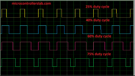
On AM as you tune through the band, the signal on pin 17 should vary in duty cycle. See image. The scope should be able to lock onto this type of signal. Is the 'cycling' you mention actually a change in duty cycle and also is the amplitude good.
(Make sure you haven't got any HF filters for triggering engaged on the scope)
If the duty cycle varies (and the amplitude should be as I mentioned before at around 4.5 volts peak above the zero volt line) then the VT line should also be varying in response to that and its DC voltage varying significantly.
If AM is really dead as well then that is suspicious with regard to the missing FM OSC signal as they are unrelated and shouldn't interact in any way.
The duty cycle we expect to see will probably (on a good tuner) be even more extreme than this and go between perhaps 5 and 95%.
The missing OSC signal on FM points to a problem in the tuner can but you also say in post #1 that AM reception is not working either. In the last post you mention seeing the charge pump drive signal (pin 17) cycling on AM.
On AM as you tune through the band, the signal on pin 17 should vary in duty cycle. See image. The scope should be able to lock onto this type of signal. Is the 'cycling' you mention actually a change in duty cycle and also is the amplitude good.
(Make sure you haven't got any HF filters for triggering engaged on the scope)
If the duty cycle varies (and the amplitude should be as I mentioned before at around 4.5 volts peak above the zero volt line) then the VT line should also be varying in response to that and its DC voltage varying significantly.
If AM is really dead as well then that is suspicious with regard to the missing FM OSC signal as they are unrelated and shouldn't interact in any way.
The duty cycle we expect to see will probably (on a good tuner) be even more extreme than this and go between perhaps 5 and 95%.
Attachments
- Status
- This old topic is closed. If you want to reopen this topic, contact a moderator using the "Report Post" button.
- Home
- Source & Line
- Analogue Source
- Yamaha TX540 tuner not tuning