Hi, I have a Yamaha TX540 digital tuner which will not tune in any stations on either AM or FM. All I get is static through the speakers.It used to work fine. I have checked all the voltage test points on the board and they check out fine. I cannot see any obviously blown components or any cracked solder joints. Can anyone suggest what the problem might be. I know it's not a fancy tuner but I'd like to fix it if I can. I do not have the schematic.
Glenn
Glenn
I have a Yamaha TX540 digital tuner which will not tune in any stations on either AM or FM.
If it's in both bands, it must be something simple, since they don't share any RF circuitry,
just a final audio amplifier stage.
Check the power supply voltages to start. Does the display still show the right frequencies?
Last edited:
Hi, I have a Yamaha TX540 digital tuner which will not tune in any stations on either AM or FM. All I get is static through the speakers.It used to work fine. I have checked all the voltage test points on the board and they check out fine. I cannot see any obviously blown components or any cracked solder joints. Can anyone suggest what the problem might be. I know it's not a fancy tuner but I'd like to fix it if I can. I do not have the schematic.
Glenn
If you have an external antenna and experienced a storm lately, then the front end could be toast.
Since you've confirmed that the +30V is present? The next logical step is check VT. Download the TX-550 service manual, they are similar from what I gather.
Check if "VT" is around 5V when tune to 87.5MHz and then check at 107.5MHz if "VT" is around 22V. If these checks out OK then the PLL section and FM oscillator are functional. It is possible that the FM front end has a bad solder on the "VT" trace and the only way to check this is to desolder the front end module from the mainboard and inspect it. It is low risk and no adjustments involved.
Voltages on low pass ceramic filter
I'm trying to trouble shoot a digital tuner which will not tune either AM or FM. All voltage test points on the board read as they should. I suspect one of the ceramic filters. Can anybody tell me which pins on an FM ceramic filter should measure a voltage? Also, can you test a ceramic filter using a DMM when removed from the board? Any thoughts on this greatly appreciated.
I'm trying to trouble shoot a digital tuner which will not tune either AM or FM. All voltage test points on the board read as they should. I suspect one of the ceramic filters. Can anybody tell me which pins on an FM ceramic filter should measure a voltage? Also, can you test a ceramic filter using a DMM when removed from the board? Any thoughts on this greatly appreciated.
Ceramic filters are have a near 100% reliability and need no voltage in themselves to operate. There may or may not be voltage present on the end pins, that depends on the surrounding circuit. The centre pin is usually ground. The filter will normally have a coloured dot on it such as red, blue, yellow etc and that denotes the centre frequency. It is vital that all filters in the appropriate section match.
You can not test a ceramic filter on a meter.
You can not test a ceramic filter on a meter.
A single ceramic filter failure is unlikely to kill both AM and FM reception, as they use different filters. In some receivers the AM and FM sections will be completely separate; in others they will share the IF amplifier. Maybe a coupling capacitor has failed?
What do you mean by a 'digital' tuner? One which uses digital techniques for reception, or has a digitally-controlled local oscillator, or just a digital frequency display?
What do you mean by a 'digital' tuner? One which uses digital techniques for reception, or has a digitally-controlled local oscillator, or just a digital frequency display?
Hi DF96, by digital I mean it has electronic tuning with memory together with digital display as opposed to a tuning capacitor moved by the tuning dial. It is a Yamaha that dates from early 1990s. I'll check all of the electrolytic capacitors. Which part of the board is likely to be the IF amplifier? I don't have a schematic for this particular model. Glenn
If there is no mechanical tuning cap then it will be varicap tuned (diodes that change capacitance in response to applied reverse voltage).
First check would be on the varicap supply which is usually a super stable reference of anywhere between 15 and 30 volts or so. That voltage is then applied to the diodes via a PWM (pulse width modulated) convertor which is often just either a single transistor fed from the uP or even direct from the uP.
First check would be on the varicap supply which is usually a super stable reference of anywhere between 15 and 30 volts or so. That voltage is then applied to the diodes via a PWM (pulse width modulated) convertor which is often just either a single transistor fed from the uP or even direct from the uP.
If it is a Yamaha, you need the manual/schematic. I was authorized warranty for them through that time period. One thing you get to know about them is that they like to make one section horribly complicated for no apparent reason. The section varies and I think it is an engineer showing off in turn.
What model number are you working on?
Does the frequency display make sense?
What equipment are you using to troubleshoot this?
How do you know the test points read the correct voltages?
-Chris
Edit:
The regulator for the radio section is common to both AM and FM sections. They normally use a couple transistors to switch B+ between tuners, normally front ends.
Hi Chris, it is a TX540. The digital display makes sense. I have a DMM and an ESR meter. I don't have an oscilloscope. There are voltages marked on the board at metal wire connectors. Actually, the one which states 30V is only reading 27.8V. I wonder if that is the problem. Glenn
 Threads on the same topic merged.
I doubt the 30/27 is an issue, but that value does sound like the raw varicap supply.
I wonder if it is anything like the TX 550?
VT is the tuning volts which should vary as you attempt to tune. The arrowed line will be the PWM signal I mentioned earlier and the transistor stage converts that PWM signal into a variable DC tuning voltage.
I wonder if it is anything like the TX 550?
VT is the tuning volts which should vary as you attempt to tune. The arrowed line will be the PWM signal I mentioned earlier and the transistor stage converts that PWM signal into a variable DC tuning voltage.
Attachments
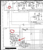
Thanks for all the helpful suggestions so far. I am learning a lot about tuners. I attempted to measure VT in accordance with comments by ej25awd and Mooly above and there seems to be a problem. I measured at the arrowed point in the schematic above (junction between middle pin of Q4 and 10K resistor and got almost no voltage at either 87.5MHz or 107.5MHz. The other pins on Q4 do have voltage (2.7V and 26.6V) which does not change with frequency tuned. Any thought on what to do next? Glenn
^ thats certainly a possiblity.
I would use a scope and look for changing PWM signal on the output of the chip (pin 17) driving that stage. As you tune the signal changes its duty cycle. That's the proof of whether the problem is before or after that stage.
If you have no scope then a meter on DC volts might show a change in voltage on that pin although its not a reliable test. If it does change then 'something' is happening, if it doesn't then it may still be OK (if that makes sense).
Hi Anatech, Chris and Mooly (and others), from checking voltages around Q2, Q3 and Q4, I think that there may be a problem with C2 (1uF 50V) which is an electrolytic or C3 (2200pF) which is a ceramic. Voltages on Q3 check out OK on all pins. More likely C2 I guess. I did check voltage on pin 17 with a DMM and there was no change as I recall. I'll double check. I can't locate C1 on the board. It is likely to be a small ceramic shaped like a resistor. There are many caps like this on this tuner. I now appreciate the value in having a schematic and being able to chase voltages. Many thanks. Glenn
'Compressed disc' ceramics, those round types that stand upright are notorious for going leaky. Tubular types, I can't just recall ever having one fail tbh. Electrolytics can deteriorate but wouldn't usually totally fail.
Do you actually have any DC voltage on pin 17 of the chip? Is the supply to the chip OK?
Do you actually have any DC voltage on pin 17 of the chip? Is the supply to the chip OK?
- Status
- This old topic is closed. If you want to reopen this topic, contact a moderator using the "Report Post" button.
- Home
- Source & Line
- Analogue Source
- Yamaha TX540 tuner not tuning