> My fault that it now sits at an angle
OK, then.
My thought was that it had got "bent" in shipping or rough storage. If yanked-off, there would be huge ripple on the tuner power line, more than the regulators could cover-up. In stone-age tuners that would cause large hum modulation; I dunno what happens with the digitals this tuner has.
But if you are sure it is in circuit and proper value, then nevermind, move on.
Hi Glenn,
This tuner should be repairable. But as punishment, you should be made to put the part in properly!")
I'm still impressed that PRR picked up on that.
Okay Glenn, where are we now with troubleshooting? Your oscilloscope is more than good enough to work on this tuner with. I used that identical model for 27 years now, since I bought it new. I believe it was around $2,500 CDN new. It is a pretty darned good 'scope with one annoying "feature", which would be that interference thing with tuners. Aside from that, it has one of the sharpest, cleanest traces I have seen on a silly-scope.
There is a modification that would allow it to remember it's last known state when you power it on again. It involves a 9V battery and a DB-9 connector. I'll have to find it if you are interested. I was too lazy to do this to my scope before I got another one to use. The power supply quit and I had to rebuild it.
-Chris
This tuner should be repairable. But as punishment, you should be made to put the part in properly!
I'm still impressed that PRR picked up on that.
Okay Glenn, where are we now with troubleshooting? Your oscilloscope is more than good enough to work on this tuner with. I used that identical model for 27 years now, since I bought it new. I believe it was around $2,500 CDN new. It is a pretty darned good 'scope with one annoying "feature", which would be that interference thing with tuners. Aside from that, it has one of the sharpest, cleanest traces I have seen on a silly-scope.
There is a modification that would allow it to remember it's last known state when you power it on again. It involves a 9V battery and a DB-9 connector. I'll have to find it if you are interested. I was too lazy to do this to my scope before I got another one to use. The power supply quit and I had to rebuild it.
-Chris
PRR, no worries and I appreciate your well considered advice. Chris, I purchased a pot today and will do some more testing on the weekend. I am happy with the scope and just ordered another Fluke probe for it on Ebay- from Israel. One odd thing though, on the CAL squarewave, the bottom part of the trace is slightly longer than the top part of the trace (along the X axis). I presume this is a calibration issue and not an issue with the screen. What do you think? Glenn
Unequal duty cycle of the Cal signal is no cause for concern. It will be that way almost certainly because it will use a standard CMOS (4xxx series) chip configured as a basic oscillator where no thought/effort goes into creating a 50:50 waveform.
The Cal output should be absolutely as marked for amplitude and it will also have fast rise and fall times to allow the probe to be calibrated.
Have a look 11 minutes in to this video. Some probes have the adjustment in the probe itself, others in the BNC connector. The adjustment only applies to the X10 setting of the probe:
YouTube
Hi Glenn,
Yes, Mooly is absolutely right on this. This test point is only there to set the probe compensation. I don't trust it with any other aspect of the calibration. You only want to look at the leading and falling edges and adjust so they are close to being a squared off edge.
That scope has a probe readout contact on the input BNC connector. When you put on a readout type probe, it will correct the vertical sensitivity readouts to reflect the fact you are using a "X10" probe. Otherwise the readout for your vertical amplitude will assume a "X1" probe. If you see any Philips probes, pick them up (they are nice probes). You only need a pair. My Agilent probe works on that scope as well (the readout feature).
I do use the cheap probes off Ebay for non-critical measurements to save the wear and tear on the nice but expensive probes. But for measurements in the RF section I will use one of my good probes.
Waiting for your update then ...
-Chris
Hi Glenn,
Sounds like the local oscillator has failed. Typically a single transistor. Often driving a buffer transistor to send that LO signal to the controller. It's rare for the actual oscillator transistor to fail, but it can happen. If you are getting an output from teh osc. out pin, it could be a cracked solder conenction.
-Chris
That doesn't right at all.
Using the scope, what is the approx frequency of this sawtooth (calculate using 1/T where T is the time period between any two similar parts of the signal).
Also what is the approx amplitude. Take the X10 probe into account. For example if the signal is 3 divisions from top to bottom (peak to peak) and the scope is set to 1mv/div then the amplitude is actually 30 millivolts peak to peak.
We need to know this just to get an idea of what you are seeing. For example it could be 100/120Hz ripple or it could be a microscopic superimposing of clock and data signals (which would be of no consequence).
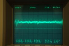
Brilliant, you can't beat a picture
That looks a little like random pickup to me, a possible artefact of the measurement setup.
Out of curiosity, if you connect the probe tip to the probe ground lead (while its connected to the tuner during the measurement) you may well still see the same noise. Might be worth just trying that. Also do you see that same kind of noise on any other pin of the tuner can.
And a bit more...
The local oscillator for the 88 to 108MHz band would run at those frequencies PLUS the IF (intermediate frequency) and so would be in the 98.7 to 118.7 MHz range.
FM tuners always use 10.7MHz IF frequencies and the IF filters are those three legged ceramic do-dahs that will be on the board somewhere.
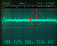
The frequency of your signal appears to be around 66 Mhz but it doesn't look a valid signal to me, more like random pickup as I mention. This is how the frequency is calculated (picture).
That said... you have no tuning voltage at the moment and so the oscillator might be running very low in frequency. I would see what happens when you artificially create a tuning voltage as we mentioned earlier by using a resistor. Does that frequency of signal you see then increase.
The local oscillator for the 88 to 108MHz band would run at those frequencies PLUS the IF (intermediate frequency) and so would be in the 98.7 to 118.7 MHz range.
FM tuners always use 10.7MHz IF frequencies and the IF filters are those three legged ceramic do-dahs that will be on the board somewhere.
The frequency of your signal appears to be around 66 Mhz but it doesn't look a valid signal to me, more like random pickup as I mention. This is how the frequency is calculated (picture).
That said... you have no tuning voltage at the moment and so the oscillator might be running very low in frequency. I would see what happens when you artificially create a tuning voltage as we mentioned earlier by using a resistor. Does that frequency of signal you see then increase.
Attachments
What I can say is that the same signal is there when I turn the tuner off so must be random pickup.
I nearly asked you to do that
honest. It just had that look about it. So its pickup and the oscillator doesn't appear to be running
No easy answers I'm afraid. I would still suggest adding a tuning voltage to put the tuner can into a 'valid' state but I suspect we are looking at an issue within the can... and that gets pretty heavy faultfinding and repair wise as RF circuitry is quite specialised and the parts used become critical.
The best repair option once we are convinced the can is at fault would be to source a new module but I suspect that is easier said than done and perhpas not viable.
No worries Mooly. It really pleases me that we have been able to identify the problem. As I said earlier, I have learned a lot during the process and now have an oscilloscope that I am gradually learning to use. A win-win situation for me (I do hate that term). Thanks again to you and Chris for your patience. I will try using the resistor to put the tuner can into a valid state and let you know what I find. A job for tomorrow. Glenn
The scope is absolutely the best diagnostic tool you have.
In that picture, the period of the signal is taken from two identical points. If the timebase is on 50ns per division then we can guesstimate the period to be around 15ns. That would give a frequency of 1/15E-9 which is approx 66MHz. I missed that bit out of the explanation I think.
Once you've made a decision on the tuner then you can always treat it as a learning project and not worry about causing problems. Have a poke around the oscillator transistors in the can and see if any anomalies show.
I will treat as a learning project. As I said earlier, I have a couple of other tuners so was not relying on this one being repaired. Having said that, it would have been nice to fix it. Thanks for the heads up on calculating frequency- takes me back to high school physics days. I have managed to repair a couple of amplifiers and receivers over the past few years with just a DMM but the scope will make repair work a lot easier. On the scope front, is it worth buying a cheap signal generator? I see you can buy them on ebay for well under $100US. Not too sure of the value in having one apart from checking calibration of the scope. Maybe an Arduino would be a better option. Glenn
Signal generators are always useful but you have to balance your needs with costs. A good function generator is handy (sine/square/triangular) and while not low ultra distortion is still extremely useful. I've one that covers from sub 1Hz to 2MHz.
For checking scope calibration remember that for the Y axis (voltage) you can use a battery and pot and a DVM. If the voltage applied is 1 volt then the trace should move the appropriate number of divisions. For the Y axis you can use electronically generated audio signals (use Audacity) to check the timebase. Thats OK for lower frequencies. For higher frequencies connect the scope to a crystal oscillator (is there one inside your tuner?) and check the display is correct by calculation.
For checking scope calibration remember that for the Y axis (voltage) you can use a battery and pot and a DVM. If the voltage applied is 1 volt then the trace should move the appropriate number of divisions. For the Y axis you can use electronically generated audio signals (use Audacity) to check the timebase. Thats OK for lower frequencies. For higher frequencies connect the scope to a crystal oscillator (is there one inside your tuner?
) and check the display is correct by calculation.- Status
- This old topic is closed. If you want to reopen this topic, contact a moderator using the "Report Post" button.
- Home
- Source & Line
- Analogue Source
- Yamaha TX540 tuner not tuning