does a low-Z load on the cartridge reduce the eddy current effects?
Or does open circuit? I hope I can find my spare carts and do a measurement. The reason I wanted to look at unloaded noise is that the resistive part on MM's is large enough that one should easily be able to resolve the self resonant frequency and Q without any electrical stimulus.
without any electrical stimulus.
How can this be done?
I found these two by the way.
measuring distributed capacitance
http://www.datatronics.com/pdf/distributed_capacitance_paper.pdf
Fig 17-11 measure with oscilloscope
https://coefs.uncc.edu/mnoras/files/2013/03/Transformer-and-Inductor-Design-Handbook_Chapter_17.pdf
George
How can this be done?
George
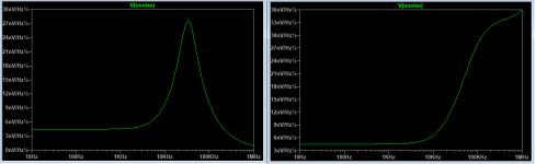
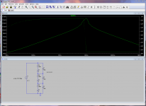
Below are two examples, I picked Rod Elliot's split L model just as an example. The first is loaded (100pF||47k) second is unloaded. Both of these are noise only. We can measure the series resistance and the basic low frequency inductance, the noise signature should reflect the loss and, if present, a resonance will give the internal parallel C.
With much difficulty I was able to measure the noise of the DA in a 50pF mica capacitor. Thermo-dynamically all electrical loss mechanisms have an associated noise.
Thanks for the references, they show the possibility of non-minimum phase in these measurements (?).
Attachments
Scott, nice plots but I haven’t understood your method.
I already knew that you are mastering the noise like no one else here, while I have no clue.
So why do I bother to ask?
Right Scott.
I have seen this in some of loudspeaker impedance measurements, 0 phase and max Z a few Hz apart.
I don’t know why it happens, what is the cause of it.
I want to test it in more details with the carts and inductors.
I prepare the measuring jig for using lower signal levels than the previous runs, hopefully going some 40dB lower.
If I fail, I know whom to ask for help.
George
I already knew that you are mastering the noise like no one else here, while I have no clue.
So why do I bother to ask?
Thanks for the references, they show the possibility of non-minimum phase in these measurements (?).
Right Scott.
I have seen this in some of loudspeaker impedance measurements, 0 phase and max Z a few Hz apart.
I don’t know why it happens, what is the cause of it.
I want to test it in more details with the carts and inductors.
I prepare the measuring jig for using lower signal levels than the previous runs, hopefully going some 40dB lower.
If I fail, I know whom to ask for help.
George
Been trying to go back a few steps on this and invoke spherical cows. Someone tell me where I'm making a wrong assumption or have physics upside down.
Assuming eddy currents exist and assuming the generator in a MM cart is so inefficient that the wiggling magnet can be ignored.
1. In 47k world eddy currents will be level dependent (possibly testable).
2. For an EC to flow in the iron core, then current must flow in the coil
3. For current to flow there must be a voltage across the windings.
4. In the low-Z world the voltage across the windings is much reduced as the voltage across the cartridge pins tends to zero and only the coil resistance limits this
5. low voltage also means low current in this case (not sure about that)
If all the above is correct then a low Z preamp will show a lot less tendency for a midrange dip
Conversely a higher Z load might increase the dip?
Load the Magnets!!! - [English] has some measurements that might indicate this is the case. Given my lack of trust for pink noise tracks on test records I consider salt is needed, but we might be onto (backonto?) something.
What have I missed?
I would expect a low impedance load is a maximum current case, not low current.5. low voltage also means low current in this case (not sure about that)....
What have I missed?
When the load is 47k or higher, the current flowing is mainly into capacitance
The Datatronics link is interesting, we have several of the problem indicators in a MM
I did too, but if you think that most carts (not the silly ones I have) have a 500Ohm to 1k5 series resistance then you not only have a current limiter, but also your ability to hold the coil near 0V drops as well. If voltage across the coil is zero current is zero in the case of a super low efficiency generator.
I am probably wrong, but it matches some very limited datapoints we have on the midband dip.
I am probably wrong, but it matches some very limited datapoints we have on the midband dip.
Another suspect to tick off the list (clutching at straws here I know). With a transamp we are rolling off anywhere from 50-500Hz first order. So by 2kHz we are at minimum 12dB down (other than Grado).
IF eddy currents are involved AND if lower level reduces eddy currents would this explain things?
IF eddy currents are involved AND if lower level reduces eddy currents would this explain things?
Another suspect to tick off the list (clutching at straws here I know). With a transamp we are rolling off anywhere from 50-500Hz first order. So by 2kHz we are at minimum 12dB down (other than Grado).
I still vote the mid-dip to be some cantilever/suspension/damping effect. The Grado looks just like the "load the magnets" plot (I trust the constant velocity track on the CBS Labs LP).
well we can test that comparing OM and superOM when I post a super body to LD. He gets a flat response on a carrtridge that gets a dip with 47k loading...
New Lamps for Old 2M has the split pins. least dip. I'm curious to chase this to a logical conclusion even if totally and utterly wrong.
New Lamps for Old 2M has the split pins. least dip. I'm curious to chase this to a logical conclusion even if totally and utterly wrong.
Scott,Below are two examples, I picked Rod Elliot's split L model just as an example. The first is loaded (100pF||47k) second is unloaded. Both of these are noise only. We can measure the series resistance and the basic low frequency inductance, the noise signature should reflect the loss and, if present, a resonance will give the internal parallel C.
With much difficulty I was able to measure the noise of the DA in a 50pF mica capacitor. Thermo-dynamically all electrical loss mechanisms have an associated noise.
Thanks for the references, they show the possibility of non-minimum phase in these measurements (?).
Could you show Rod Elliot's model that you used to create the noise image.
I have tried on the internet, but couldn't find this split L model.
Hans
Hi Bill, I think its well worth exploring theory.Been trying to go back a few steps on this and invoke spherical cows. Someone tell me where I'm making a wrong assumption or have physics upside down.
Assuming eddy currents exist and assuming the generator in a MM cart is so inefficient that the wiggling magnet can be ignored.
1. In 47k world eddy currents will be level dependent (possibly testable).
2. For an EC to flow in the iron core, then current must flow in the coil
3. For current to flow there must be a voltage across the windings.
4. In the low-Z world the voltage across the windings is much reduced as the voltage across the cartridge pins tends to zero and only the coil resistance limits this
5. low voltage also means low current in this case (not sure about that)
If all the above is correct then a low Z preamp will show a lot less tendency for a midrange dip
Conversely a higher Z load might increase the dip?
Load the Magnets!!! - [English] has some measurements that might indicate this is the case. Given my lack of trust for pink noise tracks on test records I consider salt is needed, but we might be onto (backonto?) something.
What have I missed?
Eddy currents arise in any conductor where there is a change of flux. In a MM cartridge this arises in the coil core because either a magnet waggles (moving magnet) or a pole piece waggles and disrupts a static field (moving iron). In a MI cartridge it also arises in the pole piece.
Eddy current is proportional to rate of change of flux, ie velocity of the moving part. So in vinyl playback that means instantaneous programme level, more or less.
The eddy current itself has associated flux, which acts to reduce incident flux. Then reduction in incident flux is proportional to rate of change of flux, ie programme level. So eddy current is a second order differential equation involving both velocity and acceleration of stylus motion, ie programme level and slew rate.
What shows up as effect on cartridge voltage output is proportional to rate of change of reduction in incident flux and that is a function of both velocity and acceleration of stylus motion, ie programme level and slew rate.
The effect of drawing coil current is to reduce incident flux.
In spherical cow land, one is allowed to ignore constants which in the real world determine how big the effect is and the relative importance of programme level and slew rate.
In a f sweep at constant level, programme slew rate depends on both level and frequency.
LD
Last edited:
Thanks Bill
I think in this article Rod has it backwards. He writes (2nd par below Fig.4)
“Cartridge manufacturers often use cantilever resonance to attempt to get a flat response up to the highest frequencies,”.
What I see happening is that the cantilever resonances is the cause of the anomaly in freq response which manufacturers try to compensate by trimming the electrical motor and it’s electrical loading.
He also measures and simulates with the 47kOhm resistor in series with the voltage generator and not in parallel to it.
I don’t get this.
It is a loading resistor.
George
It is straightforward in principle to devise a cantilever with a resonance well clear of the audioband, if desired.What I see happening is that the cantilever resonances is the cause of the anomaly in freq response which manufacturers try to compensate by trimming the electrical motor and it’s electrical loading.
LD
- Status
- This old topic is closed. If you want to reopen this topic, contact a moderator using the "Report Post" button.
- Home
- Source & Line
- Analogue Source
- Phono cartridge self resonance