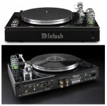
Maybe we're just missing the boat here. McIntosh MTI100 Integrated Turntable
All the bases covered, sigh. And I thought Scots were thrifty, I certainly am.
Thanks for the info Scott. And you make a good point (not that we weren't aware of it... )
At times, it is good that product design makes circles (they listen to what the broad customer base needs).
From the description, it’s not a “cheap” item (and it will sell to around $8k)
Me I'm doing really daft things. One cartridge, 3 cantilever options.
Oh Bill…
I thought that, when I realised the negative input impedance stage drives the non-inverting input of the op-amp. Then the simulator confirms, curiously, that the stage overall is inverting...…..(!?!) Phew so that's fair game at least")
Lucky, the diversion is the talk about the internals of cartridges
Thanks for the links to your coil self-resonance measurements, George. That's how I recall it. I still think that's odd though, perhaps some winding method
You are welcome.
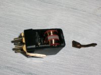
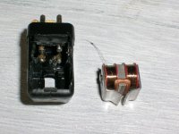
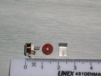
I have dissected 2-3 MM bodies.
From what I've seen, there is nothing special with the winding method.
Plain solenoid -like continuous winding in a small size. In the latest victim’s case (Stanton MK V), each of the two coils had a copper- filled cross section 4.07mmx1.97mm consisting of approx 2500 turns of AWG 39 wire (50 layers, 50 turns per layer). No bank winding, no sectioning, just continuous winding
This would equally apply to audio transformers wouldn't it, which is a better charted water?
I’ll put some chokes on the bench for to test. With transformers, on that kind of test I have to check the effect of secondary loading.
I will test them together with Bill’s ‘fat boy’ when it will arrive.
Results on the other forum or I’ll open another one specifically for self resonance
I originally though of building a distributed self resonance model via the L of one layer and the C to the next but that soon makes no sense since the C's are in series and as L grows the C goes down. I suspect the entire structure along with the mutual coupling is involved.
Scott, I think it’s not that straight.
There is capacitance between turns (Ct), capacitance between layers (Cl), stray capacitance (Cs).
Ct is in series to each other, Cl is in parallel to Ct and Cs depends on the surrounding structure
George
Attachments
Thanks that's interesting info, George. If the secondary is open circuit it should play no part - apart from the loading of its own self resonance, ironically.With transformers, on that kind of test I have to check the effect of secondary loading.
LD
Swift back of envelope calc suggests two parallel touching 1m lengths of 39 gauge enamel wire have mutual capacitance of about 42pF. Seems plausible. I don't get where this disappears to in a wound coil.
I do understand transmission lines, or so I think, but just can't find the missing piece of logic or explanation to reconcile this with what is observed.
LD
I do understand transmission lines, or so I think, but just can't find the missing piece of logic or explanation to reconcile this with what is observed.
LD
I do understand transmission lines, or so I think, but just can't find the missing piece of logic or explanation to reconcile this with what is observed.
It is an interesting problem, I think the big difference from a T-line would be the tight mutual coupling of the inductive elements. Maybe careful measurement as a lumped element is the best we can do.
..... Maybe careful measurement as a lumped element is the best we can do.
Coming from an RF background, I'm wondering why this wouldn't be an acceptable solution. Using a VNA, you should be able to get an accurate complex impedance, if that is what you are seeking. Whether it exactly models the internal workings of the coil and various capacitance shouldn't really matter, should it? The lumped element model should be the equivalent of the actual circuit and it should respond accordingly, correct? Even the complex impedance can be modeled as either series or parallel components yet produce the same results.
I'm still unclear what you are trying to accomplish. Are you trying to cancel the reactive component of the cartridge? Conjugate match of cart to preamp? Even a resistive mismatch can cause reflections and signal loss and it doesn't appear that the optimal loading (per the mfr) gets anywhere close to optimal matching.
Low Z input impedance preamps rely on audioband impedance of the coil. Whereas one might predict that could include a self-resonance of the coil, there's no evidence that it does.I'm still unclear what you are trying to accomplish. Are you trying to cancel the reactive component of the cartridge? Conjugate match of cart to preamp?
Being the curious type, I'd like to understand why - that's all I'm trying to achieve.
As to conjugate matching cart to preamp, that's one small step for man...…………..
Thankfully, such a preamp stage would still be inverting so on topic
LD
Coming from an RF background, I'm wondering why this wouldn't be an acceptable solution.
It is, just trying to rationalize expectations vs measurements. For instance any loss mechanism in the motor has noise, Rod Elliot's suggested model that supposedly includes eddy current losses would have a noise signature when doing an unloaded open-circuit measurement.
A quick look at self-resonance of good quality mic transformers suggests self-resonance at c 250kHz.
Some reference to self C not depending proportionally on number of turns, diminishing increases with each extra turn. ....
250KHz is true of low-impedance mike-iron windings. I suspect you found Jensen's 200:800 input transformer, specifically made for the low hiss-Voltage 990 amplifier.
With amplifiers of higher hiss Voltage, we wind-up to get more signal voltage. When going to a vacuum tube grid we sometimes aim over 20K ohm reflected impedance. The inductance, and leakage inductance, goes up with Z, but the C hardly changes. It is very common to find top-resonance below 25KHz, even 15KHz.
C has nothing to do with number of turns. 50 turns of house-wire, or 5,000 turns of hair-wire, both the same outside dimensions, will have very similar capacitance.
Recall that the Pickering et al 5mV 47K interface goes back to the days of tubes. It is clearly wound-up to as high an impedance as we can get with 100pFd of cable (we didn't usually put the hot-bottle preamp IN the turntable) and 100pFd of high-gain triode grid capacitance. The cartridge winding C is in there too, but I suspect it is not-large compared to cable and tube C.
Thank you, PRR that's interesting and I accept that empirically to be true.The inductance, and leakage inductance, goes up with Z, but the C hardly changes. It is very common to find top-resonance below 25KHz, even 15KHz.
C has nothing to do with number of turns. 50 turns of house-wire, or 5,000 turns of hair-wire, both the same outside dimensions, will have very similar capacitance.
What intrigues me is why ?
LD
Yes, I accept that empirically too. The reason for interest is because, in alternate topology preamps with ultra-low input Z, cable and input stage C effects are avoided. One is just left with, and relies on, coil impedance.The cartridge winding C is in there too, but I suspect it is not-large compared to cable and tube C.
It's also interesting because, if one were winding a cart for low Z input preamps and 1/f response, cartridge inductance could be increased I suppose.
LD
Last edited:
Yes, I accept that empirically too. The reason for interest is because, in alternate topology preamps with ultra-low input Z, cable and input stage C effects are avoided. One is just left with, and relies on, coil impedance.The cartridge winding C is in there too, but I suspect it is not-large compared to cable and tube C.
LD
Low-Z inputs short-out capacitive effects.
Coil capacitance is a lot about its Surface Area. Bigger coils, more C. This needs clarification: there is a C to "free space", nothing near the coil. In many practical cases there is C to a core or shield and this will be larger than the free-space C.
More reading: Transformers For Electronic Circuits, Grossner, "The wideband transformer Synthesis".
The C of guitar pickups is moderately well known. 123pFd may be a typical value. The phono pickup coil is much smaller than a guitar pickup coil, so the C would be much-much less. I'm thinking under 25pFd. Which is clearly the smallest C in a typical phono system.
Thanks that's more than interesting. So self-C is pretty much for the coil as a lumped body to the universe as a whole or the ground of the circuit involved whichever is nearer
All I can think is that as a lumped body the inductor behaves as a single turn. I can sort of get that since the mutual inductance of all turns sums. It has to be something like that.
LD
All I can think is that as a lumped body the inductor behaves as a single turn. I can sort of get that since the mutual inductance of all turns sums. It has to be something like that.
LD
I think Pyramid has a good suggestion - get it on a VNA. Also look at the screen and audio lines wrt ground.
I've been fiddling with some crude models on LTspice and its very easy to get a peak between 10k and 20k Hz of 6-8 dB with a 47k load. If you set the load at 100k or 200k, the resonant peak is 15dB (all figures ref 1 kHz). Quite how some carts are showing peaks of 20dB with a 47k load beats me though.
I've been fiddling with some crude models on LTspice and its very easy to get a peak between 10k and 20k Hz of 6-8 dB with a 47k load. If you set the load at 100k or 200k, the resonant peak is 15dB (all figures ref 1 kHz). Quite how some carts are showing peaks of 20dB with a 47k load beats me though.
Yes, that'll be interesting.I think Pyramid has a good suggestion - get it on a VNA. Also look at the screen and audio lines wrt ground.
Well, after years of figuring out how best to avoid the LCR resonance was born the ultra low Z preamp. And I sort of forgot all about the LCR hump. If the wind is blowing the right way, and with the right cart choices there need not be a lump, dip, bump in the audioband.I've been fiddling with some crude models on LTspice and its very easy to get a peak between 10k and 20k Hz of 6-8 dB with a 47k load. If you set the load at 100k or 200k, the resonant peak is 15dB (all figures ref 1 kHz). Quite how some carts are showing peaks of 20dB with a 47k load beats me though.
A few things are falling right for low Z preamps lately.....
LD
Was the mid-range dip single channel with needle up or down?
If it’s there in normal use, I’m wondering if there’s some coupling (mechanical or inductive) causing cancellation and then further up the in the top octave, the resonance peak.
I’ll have a play a bit later. Interesting problem.
If it’s there in normal use, I’m wondering if there’s some coupling (mechanical or inductive) causing cancellation and then further up the in the top octave, the resonance peak.
I’ll have a play a bit later. Interesting problem.
Putting the AT oddity to one side for a moment and looking at the dip in general. If Ortofon is right and the dip is eddy currents can anything be done to prevent them bar having a laminated core? Given LD does not seem them in his OM measurements (not sure if he has tested his S120 as well) does a low-Z load on the cartridge reduce the eddy current effects?
I've forgotten all I knew about this area of EM but if there is a plausible mechanism them that is one loose end, if not tied and least tagged for dealing with
I've forgotten all I knew about this area of EM but if there is a plausible mechanism them that is one loose end, if not tied and least tagged for dealing with
- Status
- This old topic is closed. If you want to reopen this topic, contact a moderator using the "Report Post" button.
- Home
- Source & Line
- Analogue Source
- Phono cartridge self resonance