As I know, the main difference between a RIAA Phono preamplifier and a microphone preamplifier is the RIAA network itself. Thus you need a microphone amplifier. Examples for design rules are here:Has anyone published a schematic for a Moving-magnet head amplifier that merely loads the cartridge correctly and boosts the level, but without applying any RIAA equalization?
I understand that this sort of thing is common for Moving-coil cartridges, where a step-up transformer is either too expensive or undesired for other reasons. Such a Moving-coil head amplifier is designed to be connected to the input of a MM stage with RIAA.
I listen to all music through an excellent DAC, but there is still some music in my collection that's only available on vinyl. I have written my own RIAA equalization plugin in the digital domain, and my DAC also implements optional RIAA equalization in its DSP, and I hope this explains why I want to avoid the analog RIAA circuitry.
http://www.thatcorp.com/datashts/AES129_Designing_Mic_Preamps.pdf
https://www.theseus.fi/bitstream/handle/10024/125696/Taponen_Petteri.pdf?sequence=1
But please note: if you use the DSP RIAA equalizing, the level from all kind of noise (mainly record surface noise) at your preamp output is much more higher than on preamps with integrated RIAA equalizing.
Check out this thread:
Reducing Record Surface Noise - I want to know all Approaches
Thanks! Now I see that his name is Wurcer Scott, so I can search here and there.Article is here Linear Audio | your tech audio resource
His head amp ideas are posted on here which I should have linked. Many ways to skin this particular cat!
The amount of gain is similar to a mic preamp, but a phono input is quite different from a mic input. A turntable cartridge is basically an inductor with some internal resistance.As I know, the main difference between a RIAA Phono preamplifier and a microphone preamplifier is the RIAA network itself. Thus you need a microphone amplifier.
The most important detail is that cartridge manufacturers specify a load of 47 kΩ (plus maybe 200 pF to 600 pF of capacitive load). The specifics will vary by cartridge. If the phono input does not provide the correct load, then the frequency response will vary quite greatly. I've read that if DC biasing makes its way into the phono cartridge, then it could heat up and possibly be damaged. Phantom power would be super dangerous.
Looking at the microphone amplifiers that I have available, the load varies from as little as 3.3 kΩ to 6 kΩ, 10 kΩ, or 12 kΩ, with one device that I own (which isn't really tauted for supporting a wide range of microphones) having a 200 kΩ load. None of these match the 47 kΩ load that my cartridge expects.
Granted, I could modify the mic preamp from THAT Corp to have 47 kΩ and 400 pF load, but I'd rather start from a design for a phono preamp input stage than a microphone preamp input stage.
There are two reasons for higher noise.But please note: if you use the DSP RIAA equalizing, the level from all kind of noise (mainly record surface noise) at your preamp output is much more higher than on preamps with integrated RIAA equalizing.
One of them relates to the raison d'etre for RIAA EQ in the first place: namely, that records have a lot of noise. The RIAA output reduces high frequency noise because it cuts highs. A DSP RIAA filter will reduce this noise by exactly the same amount. There could even be less noise, if enough precision is used in the DSP to beat analog filter components (which isn't difficult).
The second reason for noise depends upon how well the input stage works with the connected cartridge circuit. Douglas Self goes over a great number of details. Of the three chapters on Moving magnet phono preamps, one chapter is dedicated to noise. Most of the best options do not include any RIAA EQ in the initial stage, which is critical to minimizing the noise. My assumption is that if I get the first stage right, there's no need to include the RIAA filter because the DSP will produce less noise. Of course, this assume that the first stage isn't designed improperly, in which case all kinds of noise could be present, and the RIAA filter won't help that.
Apology to William Butler Yeats: "She bade me take life easy just as the leaves fall from the tree. But I being young and foolish, with my darling did not agree"
If you are going to write your own compensation routine via DSP put the physical T5 compensation (75us) right at the amplifier input of the first stage. That is, the loading resistor value plus the cartridge DC resistance should be equal to ZL of the cartridge at 75us.
You then get almost flat phase response which should make your job easier, and the possibility of over-loading the first stage is greatly reduced.
My bad sorry. I'd mentioned Scott's surname in post 2 and was being lazy. I should remember my own advice to not post in a rush!
@Jack. There are good reasons for flat digitising if you are post processing with a declicker. My MM does use the passive roll off but that is inherent in the implemention. All options, which is good!
@Jack. There are good reasons for flat digitising if you are post processing with a declicker. My MM does use the passive roll off but that is inherent in the implemention. All options, which is good!
Accession MM Phono Pre allows flat response:
Accession - MM Phono Preamp With Volume Control - HiFi System Components
working the math, it would appear that the Accession overload margin is only 20dB, not quite adequate.
Accession - MM Phono Preamp With Volume Control - HiFi System Components
working the math, it would appear that the Accession overload margin is only 20dB, not quite adequate.
OK I had to read 5 pages to realise that that has nothing to do with a 'flat' MM stage as the rest of us describe it. Interesting approach, but not one I would want to persue. Anyway he thinks the transamp concept is wrong, so that is another to add to the list on the back of the case 'Doug Self, John Curl and Graham Slee think this is a bad idea'.
A std INA front end should have more that enough overload margin.
A std INA front end should have more that enough overload margin.
That's very interesting. Thank you. Looks like a great product, although it's over US$1,000.Accession MM Phono Pre allows flat response:
Accession - MM Phono Preamp With Volume Control - HiFi System Components
working the math, it would appear that the Accession overload margin is only 20dB, not quite adequate.
The only downside I see is the unbalanced output. I've had so much trouble with unbalanced that I set my own rule: No more unbalanced electronics will be added to my gear collection.
I'm also designing a PCB where I can populate components to match the head amplifier to a specific cartridge, rather than have lots of switches or a volume knob. Rather than variable capacitance, I'll just have a single capacitor that is ideal for my cartridge. When I get a new cartridge, I'll just populate another board with the appropriate components. Accession makes a big deal about steel shielding, but what about the DIP switches that connect to those loading caps?
How will you know the capacitance needed beforehand? It's the whole faff with loading to get the required frequency repsonse that moved me to start down the road of using the cartridge inductance as the L in an L-R filter.
I've not tested this but reading on what other people have done it's worth adding just enough to kill the ultrasonic noise but not enough to mess too much with the HF rolloff. I need to try and capture this, but like an idiot when I re-arranged my system to get it out of the way of little ones I haven't allowed space to get a scope hooked up for this sort of testing.
With standard 47K||pf setup you end up with a 4th order rolloff somewhere between 10kHz and 25kHz. IMO this is on of the big reasons that people like MC more that MM as too much capacitance in the phono stage gives you a tone control. Even loading to give an 8kHz pole (which is what Bob Cordell did in his vinyltrak) removes most of the problem.
That's an excellent question. I'm starting with Ortofon's spec, but that's fairly wide at 200 pF to 600 pF for one specific cartridge.How will you know the capacitance needed beforehand?
I'm making several boards, so even if desoldering is a lot of hassle, I can always build a second board with a different capacitance installed. I don't want a switch because I assume that I can dial this in and then dedicate one head amp to each cartridge (some carts have identical specs, so I don't really need many variations).
I like your advice, if I understand where you're pointing, so maybe I'll start with the minimum load of 200 pF. I might try to use SPICE to simulate the input stage with a basic model of the cartridge, and see what sort of response that predicts.I've not tested this but reading on what other people have done it's worth adding just enough to kill the ultrasonic noise but not enough to mess too much with the HF rolloff. I need to try and capture this, but like an idiot when I re-arranged my system to get it out of the way of little ones I haven't allowed space to get a scope hooked up for this sort of testing.
I have a couple of 'scopes, but no test records with known frequencies. I suppose that I could generate test signals, but then my source would need to simulate the inductance and resistance of the cartridge.
I think this might describe what went south with my passive solution. I had capacitors in there for a while, and the setup "sounded" flat. But then when I switched to another interface, it sounded dull, so I removed the capacitors. Now I'm back to getting unpredictable results.With standard 47K||pf setup you end up with a 4th order rolloff somewhere between 10kHz and 25kHz. IMO this is on of the big reasons that people like MC more that MM as too much capacitance in the phono stage gives you a tone control. Even loading to give an 8kHz pole (which is what Bob Cordell did in his vinyltrak) removes most of the problem.
It's like night and day when the passive adaptor doesn't work. Once I get past that, though, I'll probably obsess with perfection that might not be so readily audible.
As I mentioned, I assume that the active circuit will be less variable when changing the final output load. I might not be able to predict the capacitance needed beforehand, but whatever I use should at least be consistent from one playback to the next.
I tend to listen to digital sources most of the time. Playing vinyl is such a rare incidence that I tend to forget which input I was successfully using, and how everything was set up.
Thanks for all of the thoughts, folks. I hope to summarize what I've come up with so far, before too long.
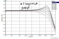
You might have 50pF from the tonearm cable and 150pF in the connecting cable to the preamp. Attached is a simulation Luckythedog did some years back for an AT cartridge. Now reality as measured often seems worse but the more I see the more I realise that a lot of test records are not as accurate as we hope. In reality you often see a midrange dip before the HF peak.
Of course most commercial phono stages don't even quote their input capacitance. Holmann had realised this in 1976.
If you can get you flat amp stage as close to the TT as possible then I think you have a plan, but a dip switch with some capacitors works well so I would not hamstring yourself.
Or just resistivily load until C is no longer and issue, which is the way i have gone.
Attachments
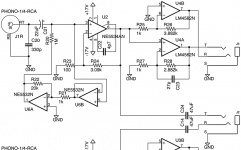
Here is what I have so far. See the attached schematic.
The 330 pF load capacitor will be reduced to 200 pF for starters.
The 1 MΩ input resistor is anti-bootstrapped to reduce Johnson noise on the input, since the typical 47 kΩ load resistor would produce more noise.
The power supply is ±17V for all three op-amps.
The NE5534AN has great noise performance for a turntable cartridge preamp, and it's output is roughly -10 dBV with this gain setting.
The NE5532N is a reasonable compromise dual op-amp that buffers the input from the 1 kΩ gain resistor.
The LM4562N stage is used to produce a balanced output at +4 dBu. Rather than the common balanced stage that inverts the signal twice, but would seem to add multiple stages of noise, this topology splits the signal and sends it through both inverting and non-inverting gain stages. The noise from either half is not boosted by the other half, and it should be reduced by 3 dB when the balanced signal is received. The balanced outputs are DC coupled because I know that my ADC can handle this (it presents a 10 kΩ load). I'd like to discuss balanced output topologies in another thread...
Attachments
Have you read Bob Cordell's notes on cooled loading? http://www.cordellaudio.com/preamplifiers/vinyltrak.shtml
For the output my illogical preference is a cross-coupled output using THAT1240.
For the output my illogical preference is a cross-coupled output using THAT1240.
The 1 MΩ input resistor is anti-bootstrapped to reduce Johnson noise on the input, since the typical 47 kΩ load resistor would produce more noise.
Keep in mind that you can't get below the cartridge noise. In a SPICE simulation the RIAA equalized noise of a Shure V15V cartridge is about 650 NV over the 20-20kHz bandwidth. If you amplifier produces less noise than that you aren't going to obtain a much benefit by reducing the amplifier noise further.
Keep in mind that you can't get below the cartridge noise. In a SPICE simulation the RIAA equalized noise of a Shure V15V cartridge is about 650 NV over the 20-20kHz bandwidth. If you amplifier produces less noise than that you aren't going to obtain a much benefit by reducing the amplifier noise further.
Ray: Reason I asked was that Bob puts the gain first, then the inverting stage as a follower. I've not dug into why that is better/worse, just noting it. A cooled load as Bob noted is useful if you are going to load down the cartridge to give a passive 75uS pole. Either way good to get these alternative approaches being discussed ") .
.
.A cooled load as Bob noted is useful if you are going to load down the cartridge to give a passive 75uS pole. Either way good to get these alternative approaches being discussed
If you consider the ITU-486 noise curve, putting the 75uS pole ahead of the first stage militates against noise in the region in which we are most sensitive.
But that's not what the thread-starter wants to do.
It isn't, just noting that is where you get the most gain from the 'cooled' approach. Hans Polak did some sims last year on this Measuring phono stage RIAA accuracy with a computer . The improvement at 47k loading is small, but very significant with a 6k load, which is about what you need to passively provide the 75uS pole.
Yes, I'm reading Douglas Self, Small Signal Audio Design, where he offers his 'Elektor Preamplifier 2012' as one of many examples. I also just noticed that Bob Cordell's VinylTrak page references the same Elektor article.Schematic reminds me of Elektor May 2012.
I've changed a lot, especially simplifying, but I kept the same op-amp choices.
It isn't, just noting that is where you get the most gain from the 'cooled' approach. Hans Polak did some sims last year on this Measuring phono stage RIAA accuracy with a computer . The improvement at 47k loading is small, but very significant with a 6k load, which is about what you need to passively provide the 75uS pole.
Thanks for pointing this out.
Rod Elliott is correct in his statement that the inductance of a phono cartridge behaves as if it were two series inductances, one with a parallel resistance which reduces Q. I would add that some of the rolloff of inductance also arises from the inter-winding capacitance of the coil. In the case of the Shure M78 cartridge its tens of pF's. (1)
So the impedance has an additional complex term -- and this explains the inaccuracy we see. Charts here -- it's a moving target.
Phono Termination Calculations and Calculator
(1) The Shure M78 is two coils in parallel for mono reproduction of the old RCA's in my collection - but it will take more abuse.
- Status
- This old topic is closed. If you want to reopen this topic, contact a moderator using the "Report Post" button.
- Home
- Source & Line
- Analogue Source
- Moving-Magnet Head Amp - without RIAA