The 1.58Meg resistor was wrong anyhow.
Gain in your case is (1+3.09/0.1) = 31.9. This figure times 47K gives 1.5Meg.
Hans
Sorry, it is 1.5Meg plus 47K.
When you use these two resistors, you can easily try what difference it makes by connecting the low side of the 47K to Gnd.
Hans
With the circuit you have in mind, you can expect an improvement in SNR of between 1dBA and 3dBA, depending on the cart you will be using.First of all, the synthetic 47 kΩ impedance is definitely supposed to reduce the Johnson noise, compared to a literal 47 kΩ resistor. I haven't done the research or the math to confirm that, but the texts and articles seem to agree.
When you tell the exact Cart figures in mH and Ohm I can give you a more precise answer.
Hans
Ortofon Nightclub Mkii : 580 mH, DC 1 kΩ, 8 mV 1 kHz, 5 cm/secWith the circuit you have in mind, you can expect an improvement in SNR of between 1dBA and 3dBA, depending on the cart you will be using.
When you tell the exact Cart figures in mH and Ohm I can give you a more precise answer.
Hans
Thanks!
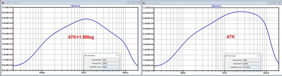
Noise in the figures below is RTI, after Riaa and after A-weighting.Ortofon Nightclub Mkii : 580 mH, DC 1 kΩ, 8 mV 1 kHz, 5 cm/sec
Thanks!
Gain from "cooling" in less noise production is 3,2dB.
Without, SNR ref 8mV is 20*log(8mV/671nV)=81.5 dBA and with it becomes 84.7 dBA.
As you can see in the noise spectra, up to 1kHz both are equal, but beyond the cooled version produces less noise.
I do not understand the 330pF cap at the input, much too high for the cabling if this is what you want to visualise.
Try to keep total capacitance under 200pF to start with, before you add anything.
Hans
Attachments
Nice. Thanks.Noise in the figures below is RTI, after Riaa and after A-weighting.
Gain from "cooling" in less noise production is 3,2dB.
Without, SNR ref 8mV is 20*log(8mV/671nV)=81.5 dBA and with it becomes 84.7 dBA.
As you can see in the noise spectra, up to 1kHz both are equal, but beyond the cooled version produces less noise.
What if RIAA is done in digital domain and not analog? Does that affect the noise figures at all? (forgive me, but I don't have my thinking cap on at the moment)
I'm going purely by Ortofon's recommended 200 pF to 600 pF load, but I'll certainly start at 200 pF. I think that 330 pF was the closest cap I could find at first, but I'm sure that I can locate a 200 pF.I do not understand the 330pF cap at the input, much too high for the cabling if this is what you want to visualise.
Try to keep total capacitance under 200pF to start with, before you add anything.
Hans
It doesn’t matter noisewise whether Riaa is applied anologue or digitally.Nice. Thanks.
What if RIAA is done in digital domain and not analog? Does that affect the noise figures at all? (forgive me, but I don't have my thinking cap on at the moment)
I'm going purely by Ortofon's recommended 200 pF to 600 pF load, but I'll certainly start at 200 pF. I think that 330 pF was the closest cap I could find at first, but I'm sure that I can locate a 200 pF.
Cabling is at least 150pF, so to follow Ortofon’s instruction, start with a 47pF cap.
You can always increase this value. Just listen to what difference it makes, that will give you the answer.
Hans
It works!
I built the most recent schematic shown, along with a +/-17.5V supply, powered it up and am enjoying great sound!
I don't own the kind of test equipment that would be needed to confirm the S/N ratios, but I might try to do some testing.
If there's interest, I can try to take some photos and post them here.
p.s. I used a 220 pF cap, but have ordered assorted other values from 47 pF to just under 220 pF that will arrive soon.
Last edited:
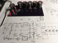
Here is the power supply. It takes in 12 V AC (I may switch to 9 V AC), from an AC wall wart with a standard barrel connector, and produces +/-17.5 V DC.
I used an AC wall wart rather than a DC wall wart so that I wouldn't have to create a virtual ground. It turned out that the circuit suffers from frequency response issues (in simulation) with a passive split rail / virtual ground setup, although that's mostly because I didn't have room in the tiny case to add an op-amp to buffer the voltage.
I used an AC wall wart rather than a DC wall wart so that I wouldn't have to create a virtual ground. It turned out that the circuit suffers from frequency response issues (in simulation) with a passive split rail / virtual ground setup, although that's mostly because I didn't have room in the tiny case to add an op-amp to buffer the voltage.
Attachments
Congrats for a DIY job well done.It works!
I built the most recent schematic shown, along with a +/-17.5V supply, powered it up and am enjoying great sound!
I don't own the kind of test equipment that would be needed to confirm the S/N ratios, but I might try to do some testing.
If there's interest, I can try to take some photos and post them here.
p.s. I used a 220 pF cap, but have ordered assorted other values from 47 pF to just under 220 pF that will arrive soon.
You should hear no noise at normal listening levels with the PU arm in the air. So why bother about SNR figures.
Noise from the LP is quite a bit above the noise level of your preamp.
What would be interesting to know, have you cosen for the split resistor solution with 47K+1M5.
In that case it would be nice to know if you notice any difference when grounding the 47K, thereby switching the "cooling" off.
Hans
I have a 1 MΩ resistor now, and have reduced the gain of the first stage to 20.1x (+26 dB) to create a virtual 47.4 kΩ load.What would be interesting to know, have you cosen for the split resistor solution with 47K+1M5.
In that case it would be nice to know if you notice any difference when grounding the 47K, thereby switching the "cooling" off.
I didn't understand what you were suggesting the first time, but I could disconnect the 1 MΩ and solder a 47 kΩ with 1 lead on the PCB and the other lead grounded. I might try that to see if there is any difference, but I doubt I could measure it.
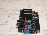
Here is the main board for the preamp. The LED hasn't been soldered on yet (still waiting for a different color).
The dimensions of the boards are constrained by the 32mm x 64mm x 104mm case that I found which has a turntable grounding screw on the outside. I didn't want to DIY the case, too.
The dimensions of the boards are constrained by the 32mm x 64mm x 104mm case that I found which has a turntable grounding screw on the outside. I didn't want to DIY the case, too.
Attachments
With the lower gain, noise improvement is now 3.0dB just a little bit less.I have a 1 MΩ resistor now, and have reduced the gain of the first stage to 20.1x (+26 dB) to create a virtual 47.4 kΩ load.
I didn't understand what you were suggesting the first time, but I could disconnect the 1 MΩ and solder a 47 kΩ with 1 lead on the PCB and the other lead grounded. I might try that to see if there is any difference, but I doubt I could measure it.
What I suggested was to use not one but two resistors in series.
In this new case 47K + 950K instead of 1 Meg.
All you have to do to notice any difference is to gnd the connection between 47k and 950k,
Hans
I like that idea! Thanks.With the lower gain, noise improvement is now 3.0dB just a little bit less.
What I suggested was to use not one but two resistors in series.
In this new case 47K + 950K instead of 1 Meg.
All you have to do to notice any difference is to gnd the connection between 47k and 950k,
Hans
Here is the main board for the preamp. The LED hasn't been soldered on yet (still waiting for a different color).
The dimensions of the boards are constrained by the 32mm x 64mm x 104mm case that I found which has a turntable grounding screw on the outside. I didn't want to DIY the case, too.
Hello, great job!. I was looking for this exact thing and found this thread. Do you have any extra boards you would be interested in selling?
Sorry for the delay - I just noticed this.Hello, great job!. I was looking for this exact thing and found this thread. Do you have any extra boards you would be interested in selling?
If you'd like boards, just order from OSH Park. I shared my design there. Looks like they're not that cheap, though, because I designed 4-layer boards.
Audio board:
OSH Park ~
Power board:
OSH Park ~
A single bjt KSA1845 works fantastic for this job, 20db gain thd < .005% 22v supply.
lower noise 2N5210 may be better.
A jfet works well but has more noise.
in this position, you are amplifying a reverse RIAA signal. 5 mv bass to 500mv treble at the output. ( 5mv @ 1khz cart)
lower noise 2N5210 may be better.
A jfet works well but has more noise.
in this position, you are amplifying a reverse RIAA signal. 5 mv bass to 500mv treble at the output. ( 5mv @ 1khz cart)
Last edited:
The whole point of this thread and project was to remove the analog RIAA filter and replace it with the digital version in my A/D converter. Now that I've built it, I'm not hearing too much treble because the cartridge is properly loaded, and the intermediate result is "flat" such that the subsequent digital RIAA restores everything to normal.
Do not use this approach if you do not have a separate RIAA filter - it will sound horribly thin!
Do not use this approach if you do not have a separate RIAA filter - it will sound horribly thin!
I'm not hearing too much treble because the cartridge is properly loaded, and the intermediate result is "flat" such that the subsequent digital RIAA restores everything to normal.
Battling to make any sense of this, care to explain? How can proper loading alone create a flat response?
- Status
- This old topic is closed. If you want to reopen this topic, contact a moderator using the "Report Post" button.
- Home
- Source & Line
- Analogue Source
- Moving-Magnet Head Amp - without RIAA