Maybe it would be a good idea to drag the cart specific parts of this thread over here:
Cartridge dynamic behaviour
I will repost the charts of the M78 analysis there.
Cartridge dynamic behaviour
I will repost the charts of the M78 analysis there.
Holy Smokes George, where has that cart been? The connections are tarnished, how would any one know if the stylus is new on that, I didn't see it.
Then I followed the link to the Cartridge dynamic behavior thread and saw some guy with a monocle doing technical stuff. I thought, it's all Greek to me.
And it really is.
")
That is really good stuff. Went from MM on this thread to the MC stuff over on that thread.
Can't we just add a low pass filter around the Neumann Pole at 42kHz and be done with it? Assuming that we'd have our RIAA equalization on a separate phono pre amp prior to our standard preamp which feeds are amp.
Isn't this what we want for an MM phono pre?
Cheers,
Last edited:
Well, there must be an explanation.
It’s either on the vinyl test record or it’s in the cart - assuming the amplifier response is flat.
I suddenly remembered that we had got some evidence of the effect. Cartridge dynamic behaviour
Now this is 'thin' evidence as it comes from Ortofon as sales blurb on their split pin models and measurements on the solid pin cartridges doesn't seem to match this (and I owe LD a split pin model to test). But it's a data point and currently unresolved.
Doug puts the inverting stage first so that the gain resistor doesn't load down the cartridge.[...] Bob puts the gain first, then the inverting stage as a follower. I've not dug into why that is better/worse, just noting it. [...] Either way good to get these alternative approaches being discussed
Bob shows two circuit variations. When implementing RIAA EQ, he shows two separate 10X gain stages because the primary stage in the signal path is not flat, so that wouldn't work for "cooling" properly. So, a second 10X gain stage that is flat is added for "cooling" separately from the 10X signal gain with the RIAA curve. If the signal path is flat, there can be a single 10X gain stage shared between the "cooling" path and signal path.
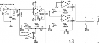
Now that you've inspired me to look at Cordell's cooling more closely, it seems that I might be able to save an op-amp stage. My signal path has a gain of 31.9X (+30 dB), so I could theoretically just feed that into the inverter instead of the extra 10X stage. I'd have to increase the resistor from 1 MΩ to 1.58 MΩ to account for the extra gain.
With output levels below 1Vrms, 500Ohm is no problem at all.I realize that I'm loading the 5534 with 500Ω, but I assume that I can recalculate all of the resistors for the gain without changing my schematic or layout - just the bill of materials.
Thank you for that detail.With output levels below 1Vrms, 500Ohm is no problem at all.
I had reviewed the data sheets, and couldn't even find a specific limit of 1000 Ω as is mentioned in many articles and books on the 5534. NJR does show a graph with maximum output voltage suffering below about 400 Ω or 600 Ω, so your comment about lower output voltage swings not suffering at 500 Ω loads makes perfect sense.
Just to be on the safe side, I recalculated my gain resistors using 2 kΩ instead of 1 kΩ. This means I no longer have an ideal -10 dBV output, but I wasn't really planning on using that output anyway. My final +4 dBu outputs are the same, after recalculation, and this means that my gain is more evenly distributed across the two stages. From what I've read, that should be good.
I now have 667 Ω total load on the 5534 output, combining the two next-stage loads and the feedback for the 5534 itself.
I've ordered a couple of circuit boards - power supply and main analog signal - plus all of the components. In a few weeks I'll be able to put all of this together. Nothing breadboarded yet, but I designed this one as 100% through-hole, so I can double-check sections of the circuit before I start soldering.
First of all, the synthetic 47 kΩ impedance is definitely supposed to reduce the Johnson noise, compared to a literal 47 kΩ resistor. I haven't done the research or the math to confirm that, but the texts and articles seem to agree.Hi RSDIO, are you sure that synthetic 47k impedance will act different than the resistor creating another rc resonance with 330pF cap? Or was it due to slightly less noise than the res?
But, to answer your question: No, I'm not sure, and actually quite confused by the circuit variations in Doug Self's book. He covers synthetic resistance, parallel resistances, and the typical capacitive load for a MM cartridge, but the variations are not explained in a way that makes it clear what tradeoffs occur between each option.
I'm not sure whether it's related to your question, but...
Some of the simplest phono circuits show only the parallel 47 kΩ resistance and 200 pF to 600 pF capacitance and then the op-amp input. This conceptually matches the data sheets from the phono cartridge manufacturers. However, I'm swayed by Doug's advice to ensure capacitive coupling between the cartridge and op-amp, to protect against DC getting into the cartridge where it might cause heating and damage. But then I get a little unclear about how much resistive load needs to be on each side of the DC blocking cap. Doug's examples show resistance on both sides.
I still haven't reviewed the EE basics to calculate the load seen by a cartridge when the load resistor is on the far side of the DC blocking cap. I'm sure it's a fairly simple formula, but it's been decades since I sat in a BSEE lecture hall.
By the way, the "complete" phono preamp circuits in Doug Self's book seem to be taken from commercial products that shipped years before the book was written. In that sense, they're proven designs that should be appropriate for a complete circuit. However, the text of the book seems to reflect more advanced research that the author has done since those commercial designs. Unfortunately, the more advanced circuit techniques don't seem to appear in the "complete" circuit designs given, so there's a bit of design understanding that has to go into synthesizing all of the information from the book into an actual working PCB. We'll see how well I've done once I've built prototypes.
Oops. Recalculating the gain for 2 kΩ loads is not what my gain split and -10 dBV output level changed. I could have kept the original gain split even with larger resistors.Just to be on the safe side, I recalculated my gain resistors using 2 kΩ instead of 1 kΩ. This means I no longer have an ideal -10 dBV output, but I wasn't really planning on using that output anyway. My final +4 dBu outputs are the same, after recalculation, and this means that my gain is more evenly distributed across the two stages. From what I've read, that should be good.
I now have 667 Ω total load on the 5534 output, combining the two next-stage loads and the feedback for the 5534 itself.
The actual reason that I changed the gain, now that I remember, is that I couldn't find a 1.58 MΩ resistor in the particular family of low-noise resistors that I'm buying. That particular line maxed out at 1 MΩ. So, I reduced the gain of the first stage, now that I redesigned the circuit to share the gain with the synthetic resistance. It was changing from 1.58 MΩ to 1 MΩ that required me to re-think the two gain stages.
But the rest of my comments about not really caring that the -10 dBV output be ideal are still accurate. I'm focused on the +4 dBu balanced outputs for my high-end ADC and DAC with digital RIAA.
In case anyone is curious, I picked the TE Connectivity / Neohm family of Low Noise Metal Film Resistors. I have no experience with them. I'm trusting that the name is accurate, or at least that they're no worse for noise than other Metal Film Resistors.
First of all, the synthetic 47 kΩ impedance is definitely supposed to reduce the Johnson noise, compared to a literal 47 kΩ resistor. I haven't done the research or the math to confirm that, but the texts and articles seem to agree.
Yes this technique is old and has been used elsewhere, the ultimate possible improvement is by square root of the R ratio and, no, negative R does not make negative noise. If you use the Norton equivalent (ideal R and noise represented as a parallel current source) it is easier to see what is going on.
The 1.58Meg resistor was wrong anyhow.The actual reason that I changed the gain, now that I remember, is that I couldn't find a 1.58 MΩ resistor in the particular family of low-noise resistors that I'm buying. That particular line maxed out at 1 MΩ. So, I reduced the gain of the first stage, now that I redesigned the circuit to share the gain with the synthetic resistance. It was changing from 1.58 MΩ to 1 MΩ that required me to re-think the two gain stages.
Gain in your case is (1+3.09/0.1) = 31.9. This figure times 47K gives 1.5Meg.
Hans
- Status
- This old topic is closed. If you want to reopen this topic, contact a moderator using the "Report Post" button.
- Home
- Source & Line
- Analogue Source
- Moving-Magnet Head Amp - without RIAA