I too have soldered probably more than a dozen of them just with a magnifying glass. It can definitely be done.
Easiest way though is with hot air. You start by using an ordinary soldering iron to melt some solder on to the pads. Then you clean the burnt flux, add fresh flux, put the IC on top, apply heat with the hot air station until the solder melts and you have soldered your IC.
Easiest way though is with hot air. You start by using an ordinary soldering iron to melt some solder on to the pads. Then you clean the burnt flux, add fresh flux, put the IC on top, apply heat with the hot air station until the solder melts and you have soldered your IC.
if you have that lying around (handy) and don't mind sharing it, I guess it would be a worthwhile addition to the thread to "visualize" where we stand now and possibly allow more understanding?
Claude
I have it but there's that one resistor bodge and some cap values changes around the LT regs because the negative LDO chip was unstable initially when with DimDim's typical widely working values. Then he experimented and he fixed the values. So I don't share it until the guys say 100% debugged in real use and redrawn to avoid confusion.
DimDim, that's clever, although I need to learn a bit more about that flux adding and cleaning... will google video
Salas, that's fair and very understanable, thanks... I will develop patience")
In fact, reading the data sheet of the regs, I was indeed wondering about the best configuration around them to avoid probs while maximising their performance for our use... very nice if DimDim has already been though it!
Thanks again to all of you
Claude
Salas, that's fair and very understanable, thanks... I will develop patience
In fact, reading the data sheet of the regs, I was indeed wondering about the best configuration around them to avoid probs while maximising their performance for our use... very nice if DimDim has already been though it!
Thanks again to all of you
Claude
Actually its Vgeorge who discovered a 10mV 964kHz LT3094 rail anomaly and Dimdim battled it to submission by manipulating values between its Vref filter cap and V- output cap. The pos LT3045 was happy with typical initial values but it now uses same caps so both polarities regs shall reach Vo nominal together at start up and having the same noise behavior.
Attachments
Motivated, I unpacked for the first time the tiny regs to hold them in my hands... God are these parts small!!! Similar to the very small Op amps I always avoided, some ARJZ and ARMZ I have lying around.
Anyway, I will have to learn to deal with these, but I guess many DIYer will be put off. That's not just SMD, that's small size SMD.
One thing seemed very curious to me: the underside contact patch. That seems to be an additional "leg" for the ground, according the spec sheet... but how did you manage to solder that one, as it is BENEATH this ridiculously small part???
Last but not least, I am amazed these regs can handle so much power dissipation, but that's not a concern anyway for this project...
Actually its Vgeorge who discovered a 10mV 964kHz LT3094 rail anomaly and Dimdim battled it to submission by manipulating values between its Vref filter cap and V- output cap. The pos LT3045 was happy with typical initial values but it now uses same caps so both polarities regs shall reach Vo nominal together at start up and having the same noise behavior.
Salas, thanks, fantastic project! I see C2 capacitors, any plans to make PCB compatible with SMD caps for those C2? I think it is Wima used (?), I guess there are Wima SMD caps available...
SMD caps, not sure they are that good nor that they survive nonexperienced hands... and what for, isn't the board small enough?
On another note, how sensitive is the Op amp for the DC offset? Why not recommending a given one that works and split it from the output stage, so that amp rolling only takes place with singles at the output stage? If one wants really to use a dual, then perhaps just to drive the 2 DC servos, while having 2 singles for each output stage?
Just thinking loud
Claude
Will probably finalize for split servo - output monoblock ICs to can do your own things freely. It may even accommodate double outline for both 5mm pitch through hole Vishay - Wima MKP & PPS-SMD 2% Panasonic (?)
As for the onboard LT tiny regs you may opt to not populate those and their few peripheral components. There is a rails socket also to can feed it externally regulated lines directly after the local tiny regs block.
As for the onboard LT tiny regs you may opt to not populate those and their few peripheral components. There is a rails socket also to can feed it externally regulated lines directly after the local tiny regs block.
Motivated, I unpacked for the first time the tiny regs to hold them in my hands... God are these parts small!!! Similar to the very small Op amps I always avoided, some ARJZ and ARMZ I have lying around.
Anyway, I will have to learn to deal with these, but I guess many DIYer will be put off. That's not just SMD, that's small size SMD.
One thing seemed very curious to me: the underside contact patch. That seems to be an additional "leg" for the ground, according the spec sheet... but how did you manage to solder that one, as it is BENEATH this ridiculously small part???
There are two ways to solder the thermal pad that's underneath the LDOs. You can either use hot air (obviously..) or use a more DIY-friendly footprint, one that has a big hole in the middle of the thermal pad. That way you can solder the LDO's pins from the top with your soldering iron and then flip the board over, put the iron in the hole and melt solder in there until you're confident that the thermal pad is soldered.
Either way is more or less fine..
Last but not least, I am amazed these regs can handle so much power dissipation, but that's not a concern anyway for this project...
In one of my boards (XMOS USB receiver) I use an LT3045 to drop from 5V to 1V at almost 300mA. That's 1.2W of heat. The LDO itself doesn't even get hot. The thermal pad though is soldered on to the ground plane, which has substantial area, since the board is a 4-layer design.
So it's all about being able to sink the heat to as big a surface as possible.
But like you said, in our application heat is really not a concern. I see about 36mA of total current draw per rail with both channels powered.
Many thanks Dimdim, very interesting
That hot air method sounds complicated, so let's hope the boards will come with the DIYer friendly hole in the middle, as otherwise soldering that chip is going to be even more of a nightmare
At the end of the day, if that chip reg doesn't perform close to UBiB1.3, one is perhaps better off just using Salas DIYer friendly board and avoiding ALL the SMD components bare the op amps...
Just thinking loud
Claude
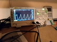
After populating the chipomatic boards and debugging a few things that were mentioned earlier in the thread finally did some listening tests in various configurations. Photos shows my test setup in old case I had.
My cart is an Audio Technica ART-9, so i needed either input mc transformers or to set up the chipo with at least 56 dB gain.
First test was with gain at 45 dB (Rg 33ohm) and some Partridge 12 dB transformers I had in my stash.
Also changed the last IC with ad823, as it was much more natural and less technical sound than with opa 2134. There was also a very slight buz I couldn' t get rid off, but not much as not to be able to do some initial evaluations. I concluded later that it was due to the transformers, as when i set the gain to 56dB by changing the Rg to 8.2 Ohms there was none.
Sound was natural and dynamic. Nothing like other chip phono amps I had listened in the past (with ad797 etc). Only by comparing to my simplistic it showed that some more naturalness can be attained, especially in the midrange.
Next was without transformers and gain set higher at the input chip.
This time no buz, but a little bit higher hum. Sound this time was a little bit more rough than I would like.
Conclusion is that with low MC you need transformers for a good result.
I have buy already two nice boxes to put it in, in the future but with some other transformers.
With MM - I did not listened - but with around 40dB gain it was was very quiet, and should be an excellent match.
Also try not to have a strong mains transformer near by, as you will have some interference. In the end I got a 15VA toroid and it was fine.
At the end it is an excellent phono stage for a very small investment.
Attachments
![IMG_20190216_184913[1].jpg](/community/data/attachments/677/677921-68a7fa90705bf8b10ed243d70b63a5cd.jpg)
![IMG_20190216_184841[1].jpg](/community/data/attachments/677/677966-d3bea8172feec23a6d4f31ecc0876346.jpg)
Hi George,
Very nice and detailled report, thanks for sharing!
I understand it is not your aim or priority, but perhaps instead of increasing the gain in the first stage only from 45 to 56dB you could have split the additional gain with the second stage - or even increase only the second's stage gain by 11dB... just a quick thought...
But anyway, your results are very very encouraging. Let's hope final boards will be relased soon!
I wonder though what (per channel) 2 class A biased AD825 would have given (or at least one for the second output stage and "whatever single" for the DC control)... perhaps I will have to find out myself once the board are relased.
Another thought... Having the normal sized dual AD823, or whetever best suited dual for that purpose only, controlling DC for both channels could enable complete free amp rolling with singles for the (second) output stage... that would make a double for DC for both channels - a dedicated one to that task - and 2 singles (for the second stage of the 2 channels)
Do you know any single op amp you do prefer over AD823 that could in your opinion be suitable for this fascinating project? Say improve on the slight drawback (mids naturalness) you noticed without deteriorating the remainer?
Have a nice Sunday!
Claude
Hi, I am not an expert on opamps, Salas will reply to your questions better.
Maybe an ultraBIB as power supply could or not help.
Remind you the comparison was with my simplistic with premium parts, dual mono supplies etc. not a fair one. If you hadn' t listened together maybe you wouldn ' t notice.
Maybe an ultraBIB as power supply could or not help.
Remind you the comparison was with my simplistic with premium parts, dual mono supplies etc. not a fair one. If you hadn' t listened together maybe you wouldn ' t notice.
Thanks again George
Although I have already ordred those amazing reg chips, it would be nice indeed to have a comparison on the Chipomatic between these reg chips... and an UltraBIB. Or who knows, maybe cumulating them both or whatever.
At the end it will be very interesting to see how much sound can be squeezed from this nice projectn whatever its final form!
George will have the opportunity to bring his build around at a point to listen for possible (?) differences between the hardwired prototype board build powered by the shunt and form an opinion vs the full SMD on SOTA reg chips version.
From what he described I think his assessment is on the right track. In other words an exciting op-amp phono that should not be expected to rival something like the FSP in sheer naturalness but scores many impressive hits.
Dimdim had listened to my build a few days ago when he came by to measure his work in progress. Was successful and measuring alike. He just had a 0.15dB rise in the curve after 1kHZ. But he was happy about it since his treble caps are of higher tolerance and his capacitance meter only indicative. It was set for MM on a wooden plank just to can look in it on the bench, he will eventually box it.
The input signal connectors especially should be skipped to directly solder the coax in a finished build, as I have seen they can be prone to erratic noises. Maybe that's a hint for George too (?)
He has a higher than 100dB sensitivity big horns multi-amped loudspeaker system that can easily throw any nuisances into stark relief.
+1 Salas, I am with you, this is indeed a very promising project!
Looking forward to the other reports to find out where the (small) bottlenecks are still hidden, or best options.
I have not listened to FSP sadly, but my understanding is it is already close when considering "affordable non exotic cartridge". Who knows, with a bit of fine tuning and further refinements (still some options left!), and only for MM use, leaving while at it the SE/balanced input selector (never good for small signals I guess), one can perhaps hope to get very close to the FSP unless considering very $$ MCs that might make the difference a bit more noticeable?
Exciting
Have a nice Sunday all of you
Claude
Hi again Salas,
May sound a bit silly given all the care for the PCB and loops and grounds... BUT, while at it when George pops around, on top of the comparison you mentioned, it would perhaps be nice to have a comparison between his PCB and your through hole farmer version, both fed by your UBiB to compare also the boards regardless power supplies.
'night!
- Home
- Source & Line
- Analogue Source
- Chipomatic balanced input RIAA