Many thanks Salas
The last remaining bit seems to be indeed the PS options... indeed sensitive as that could be potentialy putting off some DIYer... The heck, why not comparing with these regs, with 1 UBIB, with 2 UBIB (after all...) and why not even UBIB AND SMD REGS
Who knows what the best option is or if really relevant
VERY interesting, definitely up for board(s), be it Chipo or chipo + UBIB(s), great project
Claude
Do you want me to send you a V1_brd to try your hand on SMD meanwhile? I got a spare.
Of course!
I would welcome with pleasure a board and your BOM (to follow exactly your parts recommendations)
I would though also buy some SMD training kits on ebay: would be a real pity to waste my endless clumsiness on your nice boards!
Thanks a lot Salas!
Claude (more pm)
I would welcome with pleasure a board and your BOM (to follow exactly your parts recommendations)
I would though also buy some SMD training kits on ebay: would be a real pity to waste my endless clumsiness on your nice boards!
Thanks a lot Salas!
Claude (more pm)
Dimdim, why CB3 CB4 10n instead of 100n? Typo, or you actually put only 10n IC2 rail decouplers in your SMD build?
10n was suggested by the OPA2134's datasheet, so I went with those on the BoM and actual build.
100n might indeed be more fitting to this build - in fact that is what the AD823's datasheet suggests.
I am looking forward to get final PCBs when it is finalised, because of its size it would be perfect add-on to my Buffalo DAC (basically phono stage is a passive component in a sense, there is nothing to regulate, plus current consumption is tiny) and phono stage does not deserve a separate case and place on the shelve).
As 'earing' is concerned, I would recommend listening in headphones (decent ones with decent amp), since they easily show any improvements, imperfections etc, particularly those with notorious reputation for details (such as Sennheiser HD800, some AKGs).
As 'earing' is concerned, I would recommend listening in headphones (decent ones with decent amp), since they easily show any improvements, imperfections etc, particularly those with notorious reputation for details (such as Sennheiser HD800, some AKGs).
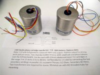
They arrived earlier. When to balance it, balance it well.
Nice! Of those currently produced these are the best ones probably.
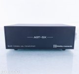
I have this step up (bought it by chance):
Attachments
Nice! Of those currently produced these are the best ones probably.
From what I saw on the bench their relatively low output impedance also permits loading around the 20kΩ mark (RL1+RL2) without significant loss of their nominal gain, showing good flatness in combination with the RIAA curve. I did not try any lower loading as for now. That ability can be used to reflect lower loading impedance for the MC cart connected on the primary side. My 10Ω (output Z) cart seems to prefer that range for instance (in subjective terms at least).
At 47k typical secondary load I did not hear any catchy difference to the Jensen (properly terminated with its datasheet Zobel). Actually the Jensen had an overall flatter response (+RIAA) with less loss under 50Hz. While the Sowter tends to a slight rise towards HF at 47k (not readily audible) which nonetheless visually improves to insignificant at circa 20k load.
The instrumentation amplifier's input bias currents now can find a lower impedance path through the Sowter's middle tap to ground, so I disconnected the ground point from the middle of RL1 RL2, and as expected there comes a mild improvement in LF noise too. Again nothing readily audible since its very low with the two wire output Jensen too.
Not needing a Zobel as termination on the Sowter's secondary side (Cz Rz reserved pads on the Chipo) is another thing that makes matters simple for trying different secondary loading. I verified there are no peaks on square-wave corners without an RC for the 1480 type indeed.
The particular samples seem to also have a slight difference in gain ratio but nothing crucial.
Overall this Sowter model although bulky and somewhat expensive is technically flexible and in good cooperation with the Chipo. Recommended.
Hi all
It is unusual for me to post on a unit before having listened to it, but as listening impressions can be very subjective and the main thing about this built is more its assembly, why not posting yet already and share experience? Especialy as I feel this thread deserves to be resurrected.
First of all I have to express my biggest thanks to Nick aka Salas, who is a true gent and who has been VERY helpful on all accounts, not only providing the board kindly but also helping me debugging it… or kind of, more of this later. My thanks also to his 2 fellows who built the Chipo before me and were also helpful developing it. Their posts guided me.
A bit of history… When Salas launched the Chipo thread I had made plans and calculations for a similar phono pre, with top parts, 2 op-amp stages, passive filtering… well, nothing new. That would have been my first design and whereas I am confident it would have worked it would have been nowhere close to what Salas with his experience in Phono pre matters can achieve. Nick was kind enough to run simulations of my project and to outline, as posted here, that it would probably have sounded a tiny tad thin. Now his Chipo design offered a (close in mind) ready to go solution built by an experienced and trustful developer, plus it opened some interesting new paths in terms of first stage measurement op-amp and LDO regulation, so a step farther than my classical project. The Chipo has also an interesting little footprint and probably a good loop immunity. For me though it had its downsides such as being SMD (never soldered these tiny parts!), not classical PS as I wanted (more familiar) and using not the best devices I wanted in terms of passive filtering. But so do other reputed units and at the end we shall see that the latest in terms of parts is probably less important than measurement and adjusting tolerances. Oh, and I wanted different decoupling cap values for the op-amps, based on my experience this time, pretty sure about that… but the Greek team already addressed that in later testings. Plus I needed an adaptation board to run single op amps in the last stage, no drama, easy to address. So at the end it was all green, a nearly perfect candidate for me and I was very lucky to get one of the prototype boards (thanks again Nick), well noting a little bug needed correction and it was just to find out...
On the positive, the board is well built, it is a robust design and yes, despite the tiny parts, it is doable!!! I had not been active with a soldering iron since the last century (!) and I managed to make it work, so shall you!
On the negative, it is much more difficult to build than an usual kit and you may need special equipment, or special processes, to really find out if you succeeded or not. More on that later.
As of the sound and the development I plan (some op rolling and other minor tweaks), you and I will have to wait to find out… as the assembly comes first...
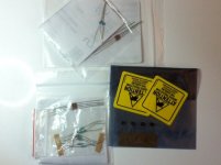
The built was done for MM purpose only, so no need to populate all the board.
Before tackling the Chipo assembly, I decided I needed to get started again after several decades and also to train on SMD parts. Especially as the board Nick sent me was really top quality and deserved something different than me learning on it. Top notch really, nice piece of board I must say, nice and tiny.
Therefore, I built a few Chinese though hole kits, the B1 KORG (great pre !), a couple of SMD soldering kits. DESPITE that, I would say that the B1 KORG is a very easy built and easy to tweak, a few hours work, whereas building the Chipo took me 15h. OK, I confess I checked everything twice and also whereas the soldering of the first tiny LDO took me 1h the last one took me 15min. BUT, I rate this built 10 times more difficult than the B1 Korg, so you have been warned. Should I have to build a second one then the soldering bit alone would probably this time take me only 5h as I learned a lot, but not less I fear… I have at this stage to take my heat off to the Greek team who succeeded in soldering the board in 2.5h… they are from another planet, for sure!
I outline again, this is not an easy built, and at the end not because of most SMD parts (once you got the trick it is actually easy to work with) but mainly because of the ridiculously small LDOs. I used a 3x magnifying glass with light, was happy to have a 10x aswell, a 0.3mm soldering tip and syringe flux as recommended by Salas. You will need all that to have a chance to succeed IMHO. Amazingly, once you have the magnifying glass, your hand gets steady and goes where you look at… eventhough we speak 0.3mm precision soldering here. Flux enables you to design / sculpture with solder, as you will need that for the tiny legs in case of corrections. It makes your life really easier for SMD parts, I had never used flux in my life, a discovery.
Dimensions had been posted but when you receive the board and the parts I got a shock! This is all really tiny, it is ants dimensions! The board holes you see on the picture are 3mm holes or so… have I said everything is tiny? I lied, it is VERY VERY SMALL at human and mere mortal scale. But it can work, again, I never did all that in the past and succeeded…
I started with the LDOs, by far the most difficult to solder and the smallest legs. I did this because if I failed I had a B plan (provision is made to power the board elsewhere) and also because it so difficult that you really want 100% access and nothing to worry about around. It took ages, I followed the vids on youtube and at the end decided to use point by point leg soldering, not saying I didn’t use the wave technique by mistake a couple of time and it worked aswell. Just do your best. Patience and good eyesight are key. They are a pain to solder, not even mentioning the back side that needs also doing. I thought for sure I had cooked them after all these tries, but they worked. Once done, I decided to solder the other tiny op-amp and from there on to work best I could.
That meant starting in one direction (progress from left to right in my case) on the board and also populating the usual SMD parts first around the chips, a bit like a growing spiral, as otherwise you may find out too late you can’t work your way inwards due to lack of access!
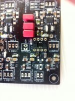
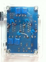
Oh, on the attached pix you will find big bridges… they are intentional! For whatever reason stupid me instead of blindly trusting a skilled Salas decided to check continuity of some LDO legs. Found problems and couldn’t solve them. Cut tracks I shouldn’t only later to find out (studying the schematic, should have started there but it was very late at night) that it was all intentional and indeed correct, so had to undo what I cut and bridge best I could.
From there on I decided to trust Salas / Nick blindly: where the parts look really way too close to be serious and so where solder is very likely to bridge… it doesn’t matter as it is mostly intended by the designer to get short paths and the parts are anyway connected already by tracks!
Build it carefully, unplug your brain and switch on special precision eyesight and care and trust your parts… Nick knows what he does, it is tiny but robust and well thought.
Before tackling the Chipo assembly, I decided I needed to get started again after several decades and also to train on SMD parts. Especially as the board Nick sent me was really top quality and deserved something different than me learning on it. Top notch really, nice piece of board I must say, nice and tiny.
Therefore, I built a few Chinese though hole kits, the B1 KORG (great pre !), a couple of SMD soldering kits. DESPITE that, I would say that the B1 KORG is a very easy built and easy to tweak, a few hours work, whereas building the Chipo took me 15h. OK, I confess I checked everything twice and also whereas the soldering of the first tiny LDO took me 1h the last one took me 15min. BUT, I rate this built 10 times more difficult than the B1 Korg, so you have been warned. Should I have to build a second one then the soldering bit alone would probably this time take me only 5h as I learned a lot, but not less I fear… I have at this stage to take my heat off to the Greek team who succeeded in soldering the board in 2.5h… they are from another planet, for sure!
I outline again, this is not an easy built, and at the end not because of most SMD parts (once you got the trick it is actually easy to work with) but mainly because of the ridiculously small LDOs. I used a 3x magnifying glass with light, was happy to have a 10x aswell, a 0.3mm soldering tip and syringe flux as recommended by Salas. You will need all that to have a chance to succeed IMHO. Amazingly, once you have the magnifying glass, your hand gets steady and goes where you look at… eventhough we speak 0.3mm precision soldering here. Flux enables you to design / sculpture with solder, as you will need that for the tiny legs in case of corrections. It makes your life really easier for SMD parts, I had never used flux in my life, a discovery.
Dimensions had been posted but when you receive the board and the parts I got a shock! This is all really tiny, it is ants dimensions! The board holes you see on the picture are 3mm holes or so… have I said everything is tiny? I lied, it is VERY VERY SMALL at human and mere mortal scale. But it can work, again, I never did all that in the past and succeeded…
I started with the LDOs, by far the most difficult to solder and the smallest legs. I did this because if I failed I had a B plan (provision is made to power the board elsewhere) and also because it so difficult that you really want 100% access and nothing to worry about around. It took ages, I followed the vids on youtube and at the end decided to use point by point leg soldering, not saying I didn’t use the wave technique by mistake a couple of time and it worked aswell. Just do your best. Patience and good eyesight are key. They are a pain to solder, not even mentioning the back side that needs also doing. I thought for sure I had cooked them after all these tries, but they worked. Once done, I decided to solder the other tiny op-amp and from there on to work best I could.
That meant starting in one direction (progress from left to right in my case) on the board and also populating the usual SMD parts first around the chips, a bit like a growing spiral, as otherwise you may find out too late you can’t work your way inwards due to lack of access!
Oh, on the attached pix you will find big bridges… they are intentional! For whatever reason stupid me instead of blindly trusting a skilled Salas decided to check continuity of some LDO legs. Found problems and couldn’t solve them. Cut tracks I shouldn’t only later to find out (studying the schematic, should have started there but it was very late at night) that it was all intentional and indeed correct, so had to undo what I cut and bridge best I could.
From there on I decided to trust Salas / Nick blindly: where the parts look really way too close to be serious and so where solder is very likely to bridge… it doesn’t matter as it is mostly intended by the designer to get short paths and the parts are anyway connected already by tracks!
Build it carefully, unplug your brain and switch on special precision eyesight and care and trust your parts… Nick knows what he does, it is tiny but robust and well thought.
Attachments
Now here and there you will need to do some corrections though, as one part needs to be connected in another way, some caps need to be staged / piled up as capacity addition is required etc.
That all works quite well with care. In fact, SMD parts are easier to work in that regard. The problem is size. Magnifying glass is key, non magnetic tweezers with different ends mandatory for all manipulations, impossible otherwise to hold a part that is 0.4mm wide and thick and solder it.
Despite that you may need a third and fourth hand. What, you have only 2? So do I… so I used also some other tweezers and blutack to have the parts I needed stacked where I wanted and to solder them in situ. Once done, I removed the (kind of melted) blutack.
As with all SMD parts, the key is to have on end of the part just solidely soldered and then to tackle the other end or the other legs. Then you go back to solder the first end properly if needed.
Attachments
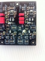
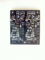
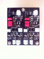
Once you are done you shoudl end up with a board looking like in the attachement. It is dirty and you will need cleaning it. USE Isopropanol and NOTHING else. I used F fuel as that works on most boards but it did a mess of mine...
While at it I decided to solder some studs to enable easy mass soldering etc.
Note that bar the LDO you could also build the Chipo as through hole version with just normal op amp adapting boards... But the Chipo once finished looks great
While at it I decided to solder some studs to enable easy mass soldering etc.
Note that bar the LDO you could also build the Chipo as through hole version with just normal op amp adapting boards... But the Chipo once finished looks great
Attachments
At that stage all you need are connections but these will also take an awful lot of time, all being tiny.
At this stage it was supposed just to be for testing purposes and having to handle it with care I didn’t want to add the trouble of tiny coax cables at the input. I have it though ready to go.
I checked and rechecked (visual inspection + multimeter) everything and it all looked perfect in theory.
It all looked good, but I didn’t want to take any chance so I decided to test it first before plugging it into my beloved HIFI system. So I used a cheap tone generator I built with a voltage divider to get a 1kHz signal with 10mV level (the lowest I could manage), had some multimeters and a cheap Chinese oscilloscope. Also an OK test HP amp and HP.
And when I plugged it all together, I had a horrible tone coming out, enable to find out what or why! I unplugged everything immediately and decided to investigate with my tone generator and cheap oscilloscope and had VERY odd results, nothing looking good but more worryingly nothing consistent!
The LDO where the most delicate parts so I suspected they went bang… but if one thing was sure, than it was that the LDO were doing a perfect job, voltage being 15V dead on.
I should have checked without my equipment simple things around shorting inputs etc. but didn’t dare doing it and TBH I was exhausted and disappointed by the project… and very short of time again.
I was clueless, the entire project had cost me more time than I wanted to spend and I was about to leave on holiday. I thought I had touched my engineer limits and should seek for external help, but the scholars I knew all ran away and said: throw it away, it either works or not.
Bad ending for sure, I was quite upset but decided to call it a day and for a minute thought RIAA amps are just to difficult for DIYer. I mailed Nick to tell him I was sorry I messed everything up but I was at the end of my competence field and could really find NOTHING wrong with the board, but obviously it wasn’t measuring well. He was surprised and offered very kindly I send the board to him for checks before really binning it.
That gave me confidence again, and I was already making plans on my own Chipo, a though hole version I could master, with my parts and my mods, so no more upset or throwing the towel that easily. But I must say this project is tough.
Attachments
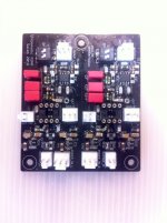
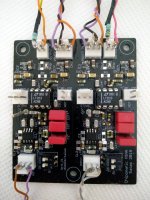
And then Nick / Salas came back to me. He had received the board. Made compliments about my soldering skills (!). Didn’t find anything wrong either on first inspection.
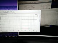
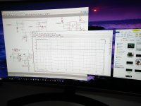
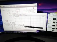
He cleaned the board (that might have been a problem indeed). Tested the board… and guess what? It PERFORMED great! +-15.000V on all regulators, filter response as it should, gain as it should, offset 0V, both channels balanced… dream performance first time on his oscilloscopes etc.
The pix attached are kindly provided by him. So my Chipo works in fact. The biggest problem might well have been my test equipment. Let’s face it, I am not equipped to generate trustfully or to measure precisely signals around the mV range (or less). Even touching a cable would mess everything up. So my odd results could also well be due to my test rig! Testing a RIAA presis just very delicate: you need truly a proper equipment to have consistent results. Salas have it and the skill to use it.
So where do we stand? The Chipo performs very well and has been tested with 2 different Op-amps of mine. These were LT1169 (just in case it blows) and LT1113 (as close equivalent I had handy to the recommended AD843). Measurement showed the RIAA curve was well within the tolerance of the components (and quite well) but a small tweak could even allow better results now we measured in real life where we are.
The Chipo is on its way back to me per post (From Greece to France back again!) and I am delighted. Great thanks to Nick!
Nick as also provided a basic test process that does only use normal equipment and which should enable to avoid silly mistakes before using the Chipo while not having ot rely on top equipment. That comes handy as, in the future when I have time again, I plan to do some testing.
The plan is to listen to the Chipo with its current OKish output Op-amps and then to use the adapter board to go for serious single op amps. My preferred option are AD825 biased in Class A, but I have made provision for more modern op-amps such as ADA4627, ADA 4625, OPA1656, OPA2134.
I will though first build a classical PS (well filtered PI stages etc.) to feed the LDO, for sure an overkill, but at least I can compare it vs my current lab PS (which is regulated and also an overkill). That will tell us at least if the LDOs are really doing a good job and cutting off any sensibility from what they get fed from. Well, the Op amps PSSR helps also for sure in that regard.
At the end I will retain the best sounding options TO MY EARS (no measurement) and hope to compare then the Chipo against 1k ready products to see how it performs.
I am afraid that will take some time as I am flat out with my work again, but I thought I shall post already to encourage other DIYer to think about building a Chipo, whereas with a board or DIY board, SMD or through hole. It is DOABLE and it looks very promising in terms of performance and possible tuning developments. And Nick / Salas is very unlikely to let you down, despite all his other projects - thanks again Nick for everything.
Have fun
Claude
PS: all these pix kindly provided by Salas, including the properly cleaned board.
Attachments
Long time since I posted here, but that shouldn’t detract us from the fabulous little projet the Chipo is !
2 main things were under investigation:
- the power supply built
- the output op amp choice
I will tackle the latter in a following post. Regarding the PS, I went for an overkill solution, that is a proper (small) tranny widely dimensioned (10x the needs), fast soft recovery diodes and a large CRC filter. Looks a bit like a 3D mess as I used existing parts and cramped boards but works (amazingly given my skills) very well. Note that they are ready existing solutions…
On main thing to consider is the output voltage. As Nick/Salas kindly raised, at very low loads (vs tranny specs) the output voltage is much higher than advertised, and that forced me to adjust the R in the CRC filter in order to get exactly 17,5V output voltage under calculated Chipo load (while still having reasonable losses)… and not a dangerously high voltage.That is my CRC filter at the end consumes as much energy as the Chipo, but then I have plenty of reserves anyway and this low level won’t kill the world. In short I had to increase my R from calculated 50R to 135R to get exactly 17,5V for any output load around the 430R mark, which is likely to reflect the Chipo needs per rail. It is still a tad higher than what I would want, but difficult to reduce that regardless the load and I hope still safe including possible short start up peaks as under 18V (for a very max rating of 20V of the LDO).
The final CRC filter per voltage rail is 4700uF – 135R – 2x3300uF, the tranny is 230V => 14V speced at 2x0.36A. Now that’s quite a CRC filter and it would on its own already provide a very clean current.
I chose a 2 board layout. The first board is offset and far away, with tranny and rectifier and 1st caps and R, for low final voltage output. Output goes into a XLR cable (several meters) leading to a second board that is mounted very next to the Chipo board, so with only low level DC and the 2x 3300uF caps per channel close to the Chipo’s LDO. Again, one probably doesn’t need all that, but I had the parts handy in case the LDO would not function…
This PS at simulated Chipo input is absolutely rock stable to the mV and an overkill as next come anyway an excellent regulation in form of a high quality LDOs on the Chipo itself. I don’t know how LDOs + small caps sound, as i twill be a first for me, but let’s say they are perfectly fed and thous should supply an even better current.
Last edited:
Next came experimenting with the output amp. The Chipo is very well made and if I would find a small improvement path that would just be to have the DC Offset op amp separated from the output op amp (for each channel). We are using 1 double op amp per channel whereas I would see a double ‘usual good op amp’ for the sole DC offset control of both channels and as addition 2 separate single op amps for each channel output. In short separating pure music output function from DC control function, eventhough both are output related and possibly affect the sonic qualities. The fact we haven’t got that forces us into some additional small boards and mountings to address the needs best we can if we want to test quality single op amps, but no drama. I didn’t play so far with having a given op amp for DC offset control and another variety for output, I may in the future although I am not sure how much the formers can affect sound… or not. So at the moment I used on the boards the same single op amps for both functions.
Initially I wanted just to swap op amps nearly on the fly diretcly on the Chipo, well knowing I had selected them before for compatibility with the help of Nick (FET input, unity gain stable, OK for +-15V supply, able to drive low R capacitive loads etc.). However, this turned to be far more complicated and time consuming than anticipated. The Chipo is tiny and its possibly fragile board with its small connections etc. mean it is OK to swap op amps very occasionaly but for sure not a benchtool to assess many op amp options without any risk. It is indeed OK to plug and unplug devices occasionaly and check if all electrical parameters are still OK before going back into my main system (to avoid disaster), but not the best tool or the safest way to assess if many op amps are indeed (still after tweaking) functioning OK or run them in or of course compare different options on the fly several times swapping them again and again.
Therefore, I decided to proceed to a preselection of op amps on another « non expensive and easy to work on » board. OK, I know op amp X can sound right in application A and not in application B whereas op amp Y would perform in application B whereas it didn’t so well in application A. BUT, to have a rough idea of sonic signatures and to proceed to an easy fail safe preselection, given some common parameters (all op amps have similar compatibility), I felt this was the best way. At the end, I don’t necessarly want a clear winner, but some winners and some potential sonic profiles to be easily confirmed or infirmed on the Chipo during quick cross checks. Say being able to reduce my real live tests on the Chipo to two or three op amps, a smaller short list.
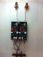
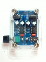
For this preselection, I built a small 47 headphone board which is mainly 2 double op amps and little else. OK, headphones are special and not « our » need /spec, so that comparo makes sense only if I use a high impedance high efficiency pro headphone (600R Beyerdynamics in my case, so not too bad vs line out requirements with my additional 100R) and if I do some tweeks to make sure close to op amp legs PS decoupling caps are OK for all possible op amps I intend to use, and also some minor tweeks on coupling caps in the signal path. Again, this is defo not a high quality board, but hopefully quality enough to see through the selectioned op amps… and if no difference is audible on HP, then differences are likely to be small unless I derive severly from the initial use. At least that’s the assumption I made. The main drawback is 3D depth sound stage is something I am not too sensitive to HP listening, while being very sensitive to it with my LS (magnetostats), but well…
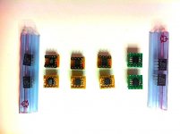
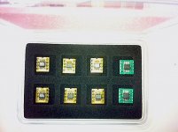
Below are some pix of the HP amp I used and also from the tiny adaptation boards I built that are of course compatible for this set up and also direct fits for the Chipo. I decided to investigate the following op amps, AD825 being a long time favourite of mine that I found better in a similar use than many other top op amps 2 decades ago when I had time to play with all that. Note I also have the possibility to bias the op amps in Class A, something the AD825 liked very much. I chose 2.4mA for the bias because in the past it proved fine for several applications, well noting it is still just Ok here for heavy duty high R HP use at my moderate listening levels.
Below are some pix of the HP amp I used and also from the tiny adaptation boards I built that are of course compatible for this set up and also direct fits for the Chipo. I decided to investigate the following op amps, AD825 being a long time favourite of mine that I found better in a similar use than many other top op amps 2 decades ago when I had time to play with all that. Note I also have the possibility to bias the op amps in Class A, something the AD825 liked very much. I chose 2.4mA for the bias because in the past it proved fine for several applications, well noting it is still just Ok here for heavy duty high R HP use at my moderate listening levels.
Attachments
Back to the competing op amps :
- LT1169 (plug in baseline, supposed to be close to AD823)
- OPA2134 (discarted for the moment as rated by other users inferior to AD823)
- LT1113 (supposed to be a better AD1169, measures very well, kind of normal size double LT1792)
- AD825 (SMD, 2 per channel, possible Class A bias, long time favourite)
- ADA4625-1 (SMD, 2 per channel)
- ADA4627-1 (SMD, 2 per channel, a lower grade alternative to AD4625?)
- OPA1656 (might struggle with capacitive load, in doubt Rout = 100R)
On the Chipo I kept for the moment an external Rout of 100R just to make sure all selected Op amps would cope and also to avoid disaster in case of mishaps. Oh, and I have also some LT1792 ready in case the LT1113 shines.
Attachments
- Home
- Source & Line
- Analogue Source
- Chipomatic balanced input RIAA