Hi again,
IMHO, your choice is nice re OP-rolling and on top most DIYer should be able to implement and additional sub-board to play between double and simple Op-amps, that is provided there is some space to do so around the board.
A few questions, if you don't mind...
1) If considering MM use only, with (my) 47k/100uF requirement re load (that's roughly what I need considering cable capacitance), is there a better choice thanAD8429?
2) Both stages are fed directly by the same PS, and I do understand that is also part of the seeked simplicity, but do you believe there is a benefit to feed the stages separately or at least to have some kind of additional buffer / regulation between them?
3) I understand OP rolling is suitable at IC2 level only with FET input types, right? 16 years ago I was very happy with the sonic qualities AD825 (single, 10x times noisier than your AD823)... But perhaps the world has moved on since, LOL, what do you think? I still use these in my DAC, polarised in Class A through... 2SK170 transisitors. Wasn't an overkill nor expensive back then, but I know these are nowadays quite rare and TBH Class A was possibly achievable only with resistors ;-)
Thanks for all this again
Claude
1) The 1nV AD8429 is great for MM and very well behaving in general.
2) The SMD test board is already dual mono in chip regs. Dual mono usually brings a small but noticeable gain in quality. This UBiB shared shunt reg did not leave much to hope for though, forceful and meaty although resolute and smooth. When it will be better wired up with shorter thicker cables it will maybe have the chance to up a further notch. Remains to be seen what happens when doubled up also.
3) AD823 is dual and not quieter than AD825 or OPA134. Its for second stage so the intrinsic noise of IC2 is mostly covered by the first stage's. When you got a socket nothing to lose with rolling. If it works well and sounds well you keep it. If not, you move to another adequate JFET type candidate.
Many thanks Salas, clear as ever !
Re point 2, I was perhaps misguided by the sonic differences UBiB 1.3 vs SMPS... Reading you again, I do now understand you had an agricultural version without any regulation on your "test board", whereas the "proper PCB" version does already include an UBiB on its board AND THOUGH the need for 2 external Salas UBiB 1.3 is not required, a simple classical linear power supply (tranny + bridge+ caps) could do the trick? And have similar results as yours with UBiB 1.3?
Is my reading correct?
Again many thanks... and defo interested!
Claude
The other style, the SMD board, includes LT3045 LT3094 SMD LDO dual mono linear regs. The big green board with the Mosfets to its side is the Ultrabib shunt linear regulator that was used soon after the SMPS stuff did not satisfy. The prototype green matrix boards agricultural build has no onboard regulators of any type. Just input DC connectors.
Hi Salas,
As said I am very interested in this project and, modestly many years ago, I gave it some thoughts myself although by far not with your knowledge nor pushing it that far.
Therefore, pardon my simple questions, my aim is just to understand better what you are doing (which is for sure state of the art) and of course not questioning your choices or the design.
I have found my old notes again, have forgotten (LOL!) why I made a few choices back then, but anyway this has highlight a few points and I was wondering if you could enlighten me…
1) In my draft, I went for an input load of 47k and 100uF as that’s ideal for MY cartridge given my cable capacity. I see you went for 48k (not sure that makes a lot of difference ?) but no capacitive load ( ?)… is that because one can add it easily or because some calculation is needed to take into account the following chip (that seem to have a very input capacity though) ?
2) I had no way to simulate my ideas, but though back then « why are people using so high resistors in the passive filter section, whereas these must generate noise and resonably low values not bring the usual associated problems ? ». My choice was also pratical and based on non SMD devices (never soldered one, that will be a first, although I would love a Chipomatic with classical parts better, bare the few ICs) and also quality parts re capacity. To make it short, R1, R2, C1 and C2 where in my project respectively 7.32k, 1.07k, 0.1uF and 0.3uF (combination of 0.1uF Vishay MKP 1837 1% tol, or Wima MKP 10 as I had good experience with these). So troughly 7 times lower R values and admittely higher C values to get it right, but I had no space issues. Were my R values a problem ?
3) I guess there must be quality low tolerance SMD resistors for so few watts, but I don’t know if there are quality SMD caps that can match the above ones, that I do rate highly in terms of sonic.
4) I wanted also to get more gain for my 6.5mV Goldring, to bring the total output to a bit higher than 1V, closer to CD / line level. That is beacuse I have a passive preamp… I like it simple with reasonable gain stages. Of course due to headroom, I must confess I went for 34 dB in the first stage, so quite close to your 36dB, but I went for 32dB in the second stage… whereas my understanding is you limit yourself to 20dB. Why so ? Simulation ? Noise seems still secondary in this stage whith these still acceptable values and headroom / stability still OK… or am I mistaken ? At least it seems easy to play with R5/R6 to adjust this…
5) One of the things that stopped me back then was the need for a proper PCB board, a multilayer with a full groundplane. Of course this can still be done manualy with foils, but can I assume you thought about a proper separate ground plane in your PCB ? I guess that is one of the benefits going small and SMD, as otherwise traditional parts on a traditional perf board as your prototype could be easier to build.
6) I like your Offset correction and PS ideas a lot. I had no DC control and re PS was thinking batteries. Now, with your project, I believe some kind of CRC LPS could be well suited. Some tranny + rectifier in a box, 2m long cables to have some R and some quality caps bypassed by small MKP ones near your board, before regulation, in the main box. Dooes that make sense… or overkill ?
7) I had some standard PS decoupling caps near the OP-amps, 22uF+0.1 MKP… is that still a good idea with a regulated PS and have you made some provision of some kind for this ? Some amps seem to be sensitive in that regard…
Sorry for the many questions in one go. I also undestand our goals might have been slightly different as indeed I wasn’t concerned by cost or space issues, so no real compromise there on my side… but also no knowledge of modern parts you are using and clear SMD avoidance")
Many thanks for all your work and looking forward for the final PCB !
Claude
As said I am very interested in this project and, modestly many years ago, I gave it some thoughts myself although by far not with your knowledge nor pushing it that far.
Therefore, pardon my simple questions, my aim is just to understand better what you are doing (which is for sure state of the art) and of course not questioning your choices or the design.
I have found my old notes again, have forgotten (LOL!) why I made a few choices back then, but anyway this has highlight a few points and I was wondering if you could enlighten me…
1) In my draft, I went for an input load of 47k and 100uF as that’s ideal for MY cartridge given my cable capacity. I see you went for 48k (not sure that makes a lot of difference ?) but no capacitive load ( ?)… is that because one can add it easily or because some calculation is needed to take into account the following chip (that seem to have a very input capacity though) ?
2) I had no way to simulate my ideas, but though back then « why are people using so high resistors in the passive filter section, whereas these must generate noise and resonably low values not bring the usual associated problems ? ». My choice was also pratical and based on non SMD devices (never soldered one, that will be a first, although I would love a Chipomatic with classical parts better, bare the few ICs) and also quality parts re capacity. To make it short, R1, R2, C1 and C2 where in my project respectively 7.32k, 1.07k, 0.1uF and 0.3uF (combination of 0.1uF Vishay MKP 1837 1% tol, or Wima MKP 10 as I had good experience with these). So troughly 7 times lower R values and admittely higher C values to get it right, but I had no space issues. Were my R values a problem ?
3) I guess there must be quality low tolerance SMD resistors for so few watts, but I don’t know if there are quality SMD caps that can match the above ones, that I do rate highly in terms of sonic.
4) I wanted also to get more gain for my 6.5mV Goldring, to bring the total output to a bit higher than 1V, closer to CD / line level. That is beacuse I have a passive preamp… I like it simple with reasonable gain stages. Of course due to headroom, I must confess I went for 34 dB in the first stage, so quite close to your 36dB, but I went for 32dB in the second stage… whereas my understanding is you limit yourself to 20dB. Why so ? Simulation ? Noise seems still secondary in this stage whith these still acceptable values and headroom / stability still OK… or am I mistaken ? At least it seems easy to play with R5/R6 to adjust this…
5) One of the things that stopped me back then was the need for a proper PCB board, a multilayer with a full groundplane. Of course this can still be done manualy with foils, but can I assume you thought about a proper separate ground plane in your PCB ? I guess that is one of the benefits going small and SMD, as otherwise traditional parts on a traditional perf board as your prototype could be easier to build.
6) I like your Offset correction and PS ideas a lot. I had no DC control and re PS was thinking batteries. Now, with your project, I believe some kind of CRC LPS could be well suited. Some tranny + rectifier in a box, 2m long cables to have some R and some quality caps bypassed by small MKP ones near your board, before regulation, in the main box. Dooes that make sense… or overkill ?
7) I had some standard PS decoupling caps near the OP-amps, 22uF+0.1 MKP… is that still a good idea with a regulated PS and have you made some provision of some kind for this ? Some amps seem to be sensitive in that regard…
Sorry for the many questions in one go. I also undestand our goals might have been slightly different as indeed I wasn’t concerned by cost or space issues, so no real compromise there on my side… but also no knowledge of modern parts you are using and clear SMD avoidance
Many thanks for all your work and looking forward for the final PCB !
Claude
1. Just a matter of resistor values available. I did not use CLoad on my handmade one because it was destined to be used with LowMC and a SUT. But I put a Zobel for the SUT's secondary to lessen ringing on square wave test. The little SMD board has both differential and single ended CLoad positions when you look closely. Because one beta testing friend has MM cart. It has SUT Zobel pads also.
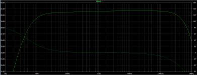
2. I used what good tolerance parts I had in my stash for a medium impedance network. 1% 1837s etc. Lower impedance passive RIAA values ask for larger components thus more loop area but still to be kept manageable. Larger value filter network caps need more fast moving current to rapidly charge especially during fast transients like clicks and pops. Slew rate and current specs of the driving chip should be examined as adequate. Your values show a rising trend towards the treble by the way. See simulation attachment.
3. Tiny good film ones available are SMD-PPS in 2% at best but some say they are prone to melt away enough tolerance if handled with bit clumsy hand soldering.
4. Headroom & noise concerns. The second stage's noise won't dominate the input one yet but like a volume control opened higher it will boost what noise floor it has been delivered to it. My DAC and TT take about same knob settings for comparable listening levels with my gain arrangement and its not that weird when you consider how records are mastered to be cut. But if with a passive line controller it may prove another story.
5. My perfboard experiment with through hole parts worked flawlessly and I can't hear any hum or hiss to speak of with Sennheiser HD 600 headphones at max volume on 10dB gain DCG3 preamp. Actually I can still distinct what's added on it's noise because I know the difference but a much younger eared friend got fooled between open input selected or Chipo selected on the DCG3 with those cans and the volume pot at full blast while the TT was spinning before lowering the needle.
That's due to the works of SUT and balanced mode input approach. It measures -80dBV 50Hz hum with a normally wired TT's output fed to the open frame agricultural Chipo after 62dB gain. If the turntable was rewired up to the cart with shielded twisted pairs on XLR terminations per channel it could even hit some -90dBV 50Hz hum spike or not. Who knows.
It normally takes a good PCB with a ground plane of course, this is just crazy one-off handwork stuff I sometimes build during rainy moonless nights.
6. Makes sense, plus some good quality low noise through hole linear reg chips could be a small sized solution to be placed near your Chipo at the receiving end of your passively filtered Raw DC scheme. As for me somehow I don't expect to hear any better combination than with the sound I now got with the big fat heat waster UBiB shunt reg. Hoping that the LT brand super low noise LDO reg chips on my friends SMD test builds will serve them somewhat alike for SQ.
7. With my handmade layout and my OP-AMP types it did not seem necessary. 0.1uF film caps close to each one's rails worked fine on the agricultural build.
Someday maybe I will also make and test a through hole Chipomatic proper enough PCB for who prefers using passive parts he can actually see.
Attachments
Hi Salas,
Many thanks for your quick and detailled response, as ever !
Got all the points all right.
Regarding...
« Larger value filter network caps need more fast moving current to rapidly charge especially during fast transients like clicks and pops. Slew rate and current specs of the driving chip should be examined as adequate. »
=> I learn something everyday, thanks. Makes sense indeed, I didn’t take that into account!
« Your values show a rising trend towards the treble by the way. See simulation attachment. »
=> Ahem, well that’s only a very small total 0.5dB rise from 20hz to 100kHz, for sure not that bad, or am I too optimistic? Or are you more concerned perhaps by the high cut off frequency and the risk to pick up garbage ?
"Tiny good film ones available are SMD-PPS in 2% at best but some say they are prone to melt away enough tolerance if handled with bit clumsy hand soldering => Well, if going SMD is not superior... why going the trouble as DIYer ;-)
Regarding point 5 : impressive, congrats again !
Is that due to the works of SUT and balanced mode input approach, or will it work well with MM aswell ? Or is at the end for MM only a « usual » high performing Op amp a better choice than the (very tempting) AD8429 ?
Having said that, I already ordered some samples from AD… and could BTW notice how very small (even by my SMD standard) the regulators are (nightmare to solder ?), much smaller than the SMD amps I am used to :-(
"Makes sense, plus some good quality low noise through hole linear reg chips could be a small sized solution to be placed near your Chipo at the receiving end of your passively filtered Raw DC scheme."
=> Ah, indeed, I was just thinking "before your proposed reg chips"… but these are indeed very very tiny, not sure I can solder them and might indeed need external help for that. Their specs are amazing though… but if one could have a « through hole » (with ground plane) PCB solution, that would be fabulous, provided a good reg could still be achieved … some kind of "light" UBiB 1.3 perhaps?
"Hoping that the LT brand super low noise LDO reg chips on my friends SMD test builds will serve them somewhat alike for SQ."
=> I will read their report with pleasure - it would be great to find out how they perform vs your UBiB 1.3
"Someday maybe I will also make and test a through hole Chipomatic proper enough PCB for who prefers using passive parts he can actually see."
=> LOL ! Thanks, that would be absolutely fabulous indeed. I don’t mind soldering a couple of SMD op amps on adapter boards to get them into the usual sockets for op rolling but that’s about my limit (at least for the moment, unless I train SMD soldering)
Again many thanks for all your kind replies, plus I learned a lot !
Have a nice day
Claude
"Ahem, well that’s only a very small total 0.5dB rise from 20hz to 100kHz, for sure not that bad, or am I too optimistic? Or are you more concerned perhaps by the high cut off frequency and the risk to pick up garbage ?"
A continuous rising trend of 0.5dB across the audio spectrum because of the many octaves energy will plainly thin out the tone in my experience. The trend already reached its high plateau level at 10kHz in the simulation. Speaker builders who have tried such a tilt with any radiation pattern HF transducer in a crossover implementation know what I am talking about. Or just run a music player on the computer with a system wide or internal EQ application also running and try that tilt on your headphones. It may compliment them or not but it should be easily discernible.
"Is that due to the works of SUT and balanced mode input approach, or will it work well with MM aswell ? Or is at the end for MM only a « usual » high performing Op amp a better choice than the (very tempting) AD8429 ?
Having said that, I already ordered some samples from AD… and could BTW notice how very small (even by my SMD standard) the regulators are (nightmare to solder ?), much smaller than the SMD amps I am used to :-("
For MM the gain is 22-26dB lower than in my LowMC application case and you should not encounter nuisance noises problems. The AD8429 proved fine and it has very good spec for MM. Regarding chip regulators there are 40uV TO-220 through hole five leg types as alternatives that can go +/-15V or more. Much easier to handle and not that much of space eaters. The OP-AMPS have strong PSRR and should still be quite happy with such spec. Example, LT1963A LT3015.
"I will read their report with pleasure - it would be great to find out how they perform vs your UBiB 1.3"
I never heard a series chip reg sounding similar to a discrete shunt reg, they are usually different in subjective effect, but as to what signature one may prefer is another matter.
Many thanks again Salas for your detailled and very clear answer!
Bottom line for me:
- I follow your RIAA line and R and C recommendations - got your point re cumulative energy in the treble
- AD 8429 it is then! Still leaves room to fine tune DC control and the final output stage, be it together with a dual op amp... of even independently going different single op amps... great!
- Regulation seems the last sensitive point... LT1963A and LT3015 are indeed much easier to solder but their performance is average, that's very sad... Of course the perfect "price no object answer" would be two UBiB 1.3 feeding the little board and no onboard reg. Overkill maybe? You will tell... that could be tempting, but then so close to to your FSP
Or... hold on... to stick to short paths and less complexity, perhaps a new challenge for you in terms of having a "light discrete UBiB" of yours directly on the board to replace the tiny series chip reg?
Fascinating, thanks again! Defo looking for a board, whatever options are chosen in the end and following this thread with great attention
Have a nice WE
Claude
P.S.
Regarding topic #2 forgot to mention that during the breadboarding phase I had also tested with a ten times less impedance scaled filter network at a point (including 0.47uF & 0.15uF film caps) but the noise grass remained essentially at the same level. The input stage's SNR seemed to dominate. That was tested with the same gain allocation in the circuit blocks.
Regarding topic #2 forgot to mention that during the breadboarding phase I had also tested with a ten times less impedance scaled filter network at a point (including 0.47uF & 0.15uF film caps) but the noise grass remained essentially at the same level. The input stage's SNR seemed to dominate. That was tested with the same gain allocation in the circuit blocks.
Thanks for the precision... outlines again that my theoretical thoughts were not too bad, but that at the end your "triple" R values proved to be the right way, so sticking to your findings religiously
In the first post there is a general schematic, but this hasn't been updated with the full schematic you are using for the PCB board, including the switches, various possible bridges and bypasses, the regs implementation etc. - if you have that lying around (handy) and don't mind sharing it, I guess it would be a worthwhile addition to the thread to "visualize" where we stand now and possibly allow more understanding?
Having said that, I am impatient to see the final boards... and I have been browsing to see the kits to learn how to solder tiny SMD parts and what flux and tips were required etc. Seems doable with some practice ...and worth the effort given your excellent results
Have a nice evening
Claude
LOL!
Yep, that board is worth learning SMD soldering, so I will start considering it
The LT regs are really tiny even in comparison to the small op amps, pity they don't come in a bigger package... but you guys succeeded, so worth a try I guess
Enjoy music with it very much
Claude
Yep, that board is worth learning SMD soldering, so I will start considering it
The LT regs are really tiny even in comparison to the small op amps, pity they don't come in a bigger package... but you guys succeeded, so worth a try I guess
Enjoy music with it very much
Claude
- Home
- Source & Line
- Analogue Source
- Chipomatic balanced input RIAA