At your service. This is a sketch all caveats apply. The basic idea is to replace the input devices with ultra-low noise ones and use the existing ones as cascodes. I'm not sure how far down you can push the noise with this but 0.5nV should be within reach without extreme values.
The 5V below V+ cascode voltage sets the collector/drain current of the input devices, the loop forces the outputs to a negative common mode voltage like in the original Demrow version of this circuit. Typically one would use something like a simple 4 resistor/op-amp differential to single ended converter for the eventual output. The gain equation is the standard one.
An extreme case might be running the input devices at 5mA (R = 1k), and Rf = 250 Ohms, and Rg = 5 Ohms for G = 100. I have no idea if this is stable or has other misbehaviors.
Scott, is there a specific reason you choose the THAT1583 over the THAT1580? The latter seems to has the better specs…
I once had the idea to put JFET source followers in front of the THAT1580 for a non-audio-application where a high input impedance and high gain where needed
Scott, is there a specific reason you choose the THAT1583 over the THAT1580? The latter seems to has the better specs…
I once had the idea to put JFET source followers in front of the THAT1580 for a non-audio-application where a high input impedance and high gain where needed
No, I noticed too late there were two (the original sketch was done when the first was released).
What would count as "ultra-low noise" devices for this application? Something like SK170's or SK369's?
Any diff pair that can get usefully below 1nV, I seriously don't know if the 8 parallel BF862 thing brings anything to the party.
Zetex based differential front ends need care with DC balance and their Ib current offset as I have seen. Finding Hfe & Vbe matches between them is not easy too.
That reminds me I need to do one with simple trims and no matching.
")
All Mod Cons
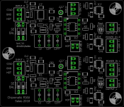
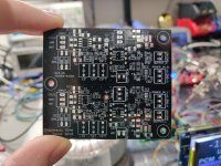
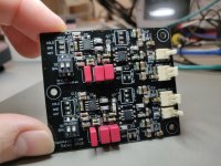
This is how the proper proto is prepared to be. Two independent channels in one 70mmx60mm board with full extras and all modern conveniences
BAL/SE input selector, SE or BAL mode cap load pads when for MM, Zobel R&C when for step-up transformer's resonance compensation, DIP/SOIC second stage OP-AMP footprints, equalized -dB auxiliary output for "creative" uses (send off to a tubez second stage?), Rout buffer resistor for long interconnects or skip it with a blob pad, LT3045/LT3094 onboard regs of fine pitch to make hand soldering life miserable, rails inserts to skip the LTs altogether and power it directly there from external regs, or to can power something auxiliary from there when using the LTs. Sadly not including 4kTV, espresso machine, and a free trip to Mykonos
Attachments
No chocolate-powder topping either ...
.
" Sadly not including 4kTV, espresso machine, and a free trip to Mykonos "
Perhaps a Lotto-Number with every board ? ...
... For a chance to win an espresso machine ?
" LT3045/LT3094 onboard regs of fine pitch to make hand soldering life miserable "

Sorry we couldn't get Tom Cruise for the 'Chipomatic' commercial.

" rails inserts to skip the LTs altogether and power it directly there from external regs "
It's a shame the board hasn't got at least 1 BIG ! space on it, for a really huge macho sized heatsink.
On the upside ... I suppose there will be plenty of room left in the 4U 19" case to install one off-board.
Si.
t.S.E.c
.
.
" Sadly not including 4kTV, espresso machine, and a free trip to Mykonos
"Perhaps a Lotto-Number
with every board ? ...... For a chance to win
an espresso machine ? " LT3045/LT3094 onboard regs of fine pitch to make hand soldering life miserable "
Sorry we couldn't get Tom Cruise for the 'Chipomatic' commercial. " rails inserts to skip the LTs altogether and power it directly there from external regs "
It's a shame the board hasn't got at least 1 BIG ! space on it, for a really huge macho sized heatsink.
On the upside ... I suppose there will be plenty of room left in the 4U 19" case to install one off-board.
Si.
t.S.E.c
.
Attachments
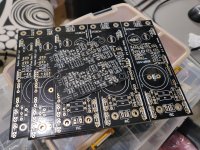
Eagle eyed lads (well... with microscopes or magnifiers) dimdim and Vgeorge are already equipped with those surface mount pcb thingies and a full BOM of tiny parts to build and use for a test. Yeah, good luck guys if there's a bug. Only in case I missed something in the prototyping
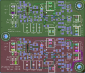
Me I kept a couple of those also but I will just finish a matrix green second channel copy for now not to throw the first one in the trash bin
Me I kept a couple of those also but I will just finish a matrix green second channel copy for now not to throw the first one in the trash bin
Attachments
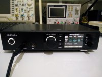
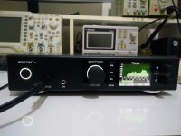
Meanwhile, heretically to analogue, evaluating...
A nice machine by any means! Lots of options on this.
Tell us your verdict when you reach to one!
- Home
- Source & Line
- Analogue Source
- Chipomatic balanced input RIAA