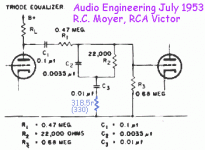
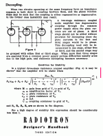
In the 1960 issue of the RCA tube manual (RCA 20) there is a passive RIAA phono stage (fig 20-16,page 216) using two 12AX7 stages. The RIAA passive filter is between the 1st and 2nd triode sections. I would like to add (per Allen Wright) a third filter stage for a 75uS (20KHz) roll off after the second tube stage. Figuring this stage is output coupled with a .22uF cap and 1M resistor and feeds into a sel switch and then a 250K volume control, what should the filter stage values be? What is the formula for figuring out these values?
Thanks for the help!
Thanks for the help!
filter for 50Khz, which I think is 3.18uS.
You would measure or calculate the circuit output impedance (before the coupling capacitor), and then add the 1M and 250k both in parallel to it, to get the total resistance R to use for the time constant. Then use C = 1 / (2Pi x R x 50kHz).
That said, this is not a good idea, regardless of how many do it. The fact that the HF response of the passive circuit goes below unity is an advantage of the passive circuit over a typical active RIAA circuit.
Last edited:
Yup..
Cygnus1 you should check out the following threads on the Eli Duttman version of the RCA passive phono stage:
Eli Duttmann's phono preamp voltages
Radiotron/Eli Duttman phono change C1 to .00391?
Cygnus1 you should check out the following threads on the Eli Duttman version of the RCA passive phono stage:
Eli Duttmann's phono preamp voltages
Radiotron/Eli Duttman phono change C1 to .00391?
....{50KHz} roll off....
You mean *boost*, to "correct" for some assumed roll-off way beyond the audio band.
My own assumption from years around the industry is that the Old Men (and the few still in the business) knew what they were doing, and they mastered to play well on the agreed playback curve. There surely was "some" limit to the cutting boost (BTW this varies across the width of the side). If that shaved 15KC or 20KC, minor extra EQ (on top of massive EQ to shake the heavy cutter) would get that top octave "right" on the playback curve everybody finally settled on.
However IF you must have the 50KHz boost, one resistor, see attached.
This is not the Tube Manual but the technical essay. The values given are SO close to perfect that I see little point teasing more digits onto them.
Attachments
PRR, thanks for schematic, but maybe I should build "as is" before adding the boost.
kevinkr, thanks I had looked at that but wanted to avoid the MosFet. I didn't think the 12AX7 would not have any problem with driving the 250K volume pot and next tube stage with 1M resistor grid resistor.
I want to employ a simple reg to start off with, either one per ch or maybe even one per section. Anyone try a simple LR8?
....maybe I should build "as is"...
I want to employ a simple reg to start off with....
IMHO: build it like it is 1952 all over again.
A tube phono preamp does not need regulation. Tubes are not fussy. 200V, 400V, works about the same. And a hair better (lower THD) at the higher voltage; a regulator just wastes-off B+ you could use to keep the tubes well fed.
A phono preamp needs LOW buzz. But it is also a LOW-current application. R-C filtering, multi-stage, will get ripple way-way down. Start from say 400V raw DC (convenient for 450V caps). Assume 1mA/triode, so 4mA. Aim for about 300V to those 2nd stages. To lose 100V at 4mA needs 25K. You can't do much better than 30:1 ripple reduction in each R-C so you probably want about four R-C stages. 25K/4 is perhaps four 4.7K resistors. For audio coupling we want 10uFd for 1K load, so 10uFd filtering on 4.7K is good, but 40uFd is also very cheap. 4.7K-40uFd-4.7K-40uFd-4.7K-40uFd-4.7K-40uFd filtering to the 2nd stages. Since caps are cheaper by the 10-pack, add two 22K resistors and two 40uFd caps to feed the two 1st stages. Including the first raw-Dc cap (which can be 40uFd) that is 7 caps down from a 10-pack leaving a few for future projects.
PRR...very cool...thanks a ton for all the help. Will try it with the R-C X 6 (if I can get it to fit in my small chassis (an old REALISTIC 33-1057A phono/mic mixer). It was the space limitation why I asked about the LR8 and I saw it somewhere, used in a DYNACO PASS. So I have ta ask... regulated heater? This is not for a MC but a MM.
I would be cautious about using a long CR smoother string for something with as much LF gain as an RIAA preamp. A simulation, or a back-of-envelope estimate, would show whether it might suffer from motorboating.
There is also mains voltage variations to think about, causing woofer flapping. The 1952 solution to both problems might involve a gas VR tube.
There is also mains voltage variations to think about, causing woofer flapping. The 1952 solution to both problems might involve a gas VR tube.
It's not going to motoboat all by itself.
There's just two amplifier stages. The sneak-back through the power rail from 2nd to 1st is negative feedback. For 100k-200k plate resistors with 10+uFd between, really tiny.
As a rough rule of thumb, two sequential stages can be fed from one node.
Or two nodes. Adjacent nodes (as I sketched) are not much different from one node. If for some reason you put multiple R-C filters between adjacent stages, the total attenuation will surely exceed the forward gain of triodes.
No doubt there is an extreme case where it becomes a phase-shift oscillator.
Attachments
Last edited:
There was a PCB of this circuit available back in the 1990s. I bought one, put in the stock RCA values but ran it with higher B+ voltage and a bit more current going through the 12AX7s. I also added a 12AT7 cathode follower on the output, DC coupled from the plate of the second 12AX7 triode. The power supply was a brute force C-R-C-R-C... type of thing (I don't remember the exact details). It wound up being perfectly quiet. I sold it around the year 2000, and had it back in my place for a checkup a year or so ago. I did some minor maintenance, replaced the older electrolytic caps. Voltages all good, so I put it into my system. It sounded really good. This is not a bad circuit at all, especially if you can put a buffer on the output to keep it from loading down into whatever amp you plug it into. (Eli D. used a MOSFET, I used a 12AT7.)
My $0.02. YMMV.
My $0.02. YMMV.
- Status
- This old topic is closed. If you want to reopen this topic, contact a moderator using the "Report Post" button.
- Home
- Source & Line
- Analogue Source
- RCA 20 Passive RIAA phono stage

