There is NO angle because there is NO pivot. It's a fixed form. It is NOT a pivot arm on the horizontal plane.
What angle do you mean? I am referring to the CAD and the different positions of the arm.
What I am not yet getting is the vectors (friction force vs the stylus point to whatever point that holds the arm in the other end). Are they 180° opposite?
What angle do you mean? I am referring to the CAD and the different positions of the arm.
What I am not yet getting is the vectors (friction force vs the stylus point to whatever point that holds the arm in the other end). Are they 180° opposite?
Your red lines are all pointing to the converging point when they should point straight 90 degrees from the spindle.
=============
Ray is correct to ask those questions. I am curious too. My suspicion is that they do pivot slightly but not passively and it's tied to the servo system. I might be wrong. If it pivots passively, then there would be skating force, I believe. Based on his 2D drawing, I measured the three distances of the front bearing to the base pivot and they're different slightly so that means something got rotated and changed the distance.
I look forward to Ralf's response.
My 2p worth is that I think the stylus sees no skate force. The headshell is effectively rigidly connected to the plinth. There is an internal torque within the arm structure, which is balanced at the point it connects to the plinth by a corresponding torque within the plinth.
LD
LD
Your red lines are all pointing to the converging point when they should point straight 90 degrees from the spindle.
Never mind my picture at this moment; you have a friction force component at the tangent line of groove direction and a counter force to keep the stylus from moving away. This should be pointing against the point where the arm is fixed, pivoted or not?
My 2p worth is that I think the stylus sees no skate force. The headshell is effectively rigidly connected to the plinth. There is an internal torque within the arm structure, which is balanced at the point it connects to the plinth by a corresponding torque within the plinth.
LD
I can understand if the force is counteracted by the internal torque of the arm/plinth and/or servo function. My initial question is if there is force and then derive the counterforce.
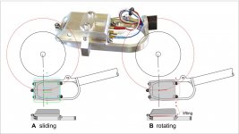
Quote Dd description: better looking (attachement) the floating headshell looks just a sliding headshell.
If it tries (and it does) to rotate it must lift on a corner: the angled bearings is a self leveling system, more than a self centering = a mini parallel linear tonearm upon a separate servo PLT base. But the winning move is the separation between the two.
carlo
Imho a parallel tracker has infinite hor. pivots (well is quite the same as no one). Here the effective length is extremely short, which is a great advantage for passive movements induced by the stylus.
Attachments
Last edited:
Hi ThomasA, here's how I see it:My initial question is if there is force and then derive the counterforce.
The skate force, and its torque, is the same as a normal pivoted arm. But, the idea is, instead of being balanced by a force on the stylus as in a normal arm, it is balanced by a torque where the arm meets the plinth.
For this to work assumes the servo is rigid, which is where potential non-ideals start I suppose. Skate force is dynamic and varies significantly with programme material - it even changes direction momentarily for high levels.
But the servo also has to effectively allow free pivot movement to follow eccentricity/warp. So success in reality depends on in the servo's ability to tell the difference between (a) skate force, which has a strong lf component inc DC, and (b) force due to eccentricity/warp.
I think the force diagram is OK if the servo can ever resolve that problem. If it has to allow free movement at lf to follow eccentricity/warp, then I suspect you are right and normal skate force mechanics applies, at least at lf.
LD
Last edited:
Hi ThomasA, here's how I see it:
The skate force, and its torque, is the same as a normal pivoted arm. But, the idea is, instead of being balanced by a force on the stylus as in a normal arm, it is balanced by a torque where the arm meets the plinth.
For this to work assumes the servo is rigid, which is where potential non-ideals start I suppose. Skate force is dynamic and varies significantly with programme material - it even changes direction momentarily for high levels.
But the servo also has to effectively allow free pivot movement to follow eccentricity/warp. So success in reality depends on in the servo's ability to tell the difference between (a) skate force, which has a strong lf component inc DC, and (b) force due to eccentricity/warp.
I think the force diagram is OK if the servo can ever resolve that problem. If it has to allow free movement at lf to follow eccentricity/warp, then I suspect you are right and normal skate force mechanics applies, at least at lf.
LD
Thanks LD; I think as you say there is an "inwards force" and the counterforce equals servo/arm/plinth "torque". So even if the forces are there as in the standard pivoted arm, they are counteracted differently to prevent skating (traditional antiskate mechanisms in pivoted arm vs arm/plinth counterforce). But still need som thinking of this to understand.
(Eccentricity I thought was dealt with in the moving headshell function (since it is a force left right, as opposed to the friction force so I think they are separate issues.)
Last edited:
As far as I can tell, the headshell is rigidly attached to the support arm. So I think errors like eccentricity are either mopped up by the servo repositioning the arm, or by allowing conventional free pivoting below a certain frequency (hence the potential issue).(Eccentricity I thought was dealt with in the moving headshell function (since it is a force left right, as opposed to the friction force so I think they are separate issues.)
The tricky bit is that the servo has to tell the difference between skate force and force due to eccentricity trying to moving the arm. It has to allow one and reject the other. But I don't think they can be separated, well not easily anyway...…..?
LD
Last edited:
Quote Dd description: better looking (attachement) the floating headshell looks just a sliding headshell.
If it tries (and it does) to rotate it must lift on a corner: the angled bearings is a self leveling system, more than a self centering = a mini parallel linear tonearm upon a separate servo PLT base. But the winning move is the separation between the two.
carlo
Imho a parallel tracker has infinite hor. pivots (well is quite the same as no one). Here the effective length is extremely short, which is a great advantage for passive movements induced by the stylus.
Excellent sketch Carlo!!
I can now see that, for small horizontal movements, the headshell behaves as a mini purely mechanical parallel linear tracker. This opens the door to even more questions:
How difficult is it to dress the short headshell leads so that they don't restrict the horizontal motion?
Is there enough loading on the cradle bearings to prevent bearing chatter?
How does it behave at the natural resonance frequencies?
Ray K
Confused, yoda is. The drawings show the headshell can slide (forward/back), and tilt. But these motions are locked rigid by retaining screws so the headshell is effectively rigidly fixed to the supporting arm? And there's no lateral motion for the headshell as far as I can see. And the support arm is held rigid to the plinth by servo?Excellent sketch Carlo!!
I can now see that, for small horizontal movements, the headshell behaves as a mini purely mechanical parallel linear tracker. This opens the door to even more questions:
How difficult is it to dress the short headshell leads so that they don't restrict the horizontal motion?
Is there enough loading on the cradle bearings to prevent bearing chatter?
How does it behave at the natural resonance frequencies?
Ray K
What natural resonant frequency is there, if nothing moves?
LD
Last edited:
the headshell behaves as a mini purely mechanical parallel linear tracker.
That's exactly what I have been trying to convey!
Dear ralf, see my pic based on you CAD. Hope it helps to understand what I wonder about.
Hello ThomasA,
The red lines in your drawing are not in the right place. You show the three lines converging in the wrong place. The actual horizontal tone arm pivot is located .415" (10.5mm) forward. The horizontal pivot of my tone arm is being constantly repositioned by the swinging support arm. The three red lines are not converging anywhere.
I hope this makes things a little clearer.
Sincerely,
Ralf
My understanding of the arm is that there's really NO horizontal pivot at all.
There is a horizontal pivot. It is just not visible. The support arm pivots in the VTA tower, and the other end of the support arm contains the horizontal pivot of the tone arm.
If the cradle is, hypothetically, 4 inches wide at a curve, you wouldn't even need a servo.
I considered that idea early during my prototype work, but discarded it because I wanted to maintain the classical appearance of pivoting tone arms. Also that four inch long track would take up a lot of space, trying to pivot it out of the way when changing records.
The servo is not there to correct error like most servo arms. It does not do the usual "crabbing" across record a la Goldmund. The servo is there to extend the runway for the floating headshell and it just so happens that its motorized base move pivotally. As the headshell starts floating in towards the spindle, the cradle eventually runs out of space for the headshell to glide on, therefore the servo tells the motor to pivot inwards. Therefore, the servo is not correcting error, it is to extend the path way. If you don't have a motor, you can nudge the armbase forward every 30 seconds or so and it is indeed what Ralf did at the early stage of the design. And the vertical arm also provides the floating headshell a way to apply tracking force. The arrangement of the 5 ball bearings allows the headshell to glide only in and out of the record center but inhibits it to move forward and backward so it's not totally free "floating". It's more of a gliding headshell. On the horizontal plane, there's no rotational movement or pivoting for the headshell on the cradle. And in Ralf's 2D drawing, it shows no pivot point at the base of the vertical arm.
You got that exactly right, except for the last sentence.
So far that's my understanding of it and I could be completely wrong and/or I'm sure I have missed some details. By the way, I think the design is brilliant.
That's a pretty good analysis all the way around. thank you.
Sincerely,
Ralf
Ralf,
On second thought, information in subsequent posts makes me suspect I had initially made erroneous assumption(s) about how the arm works, and I'm now reaching for my string. Let me play "20 questions". Here are my first few:
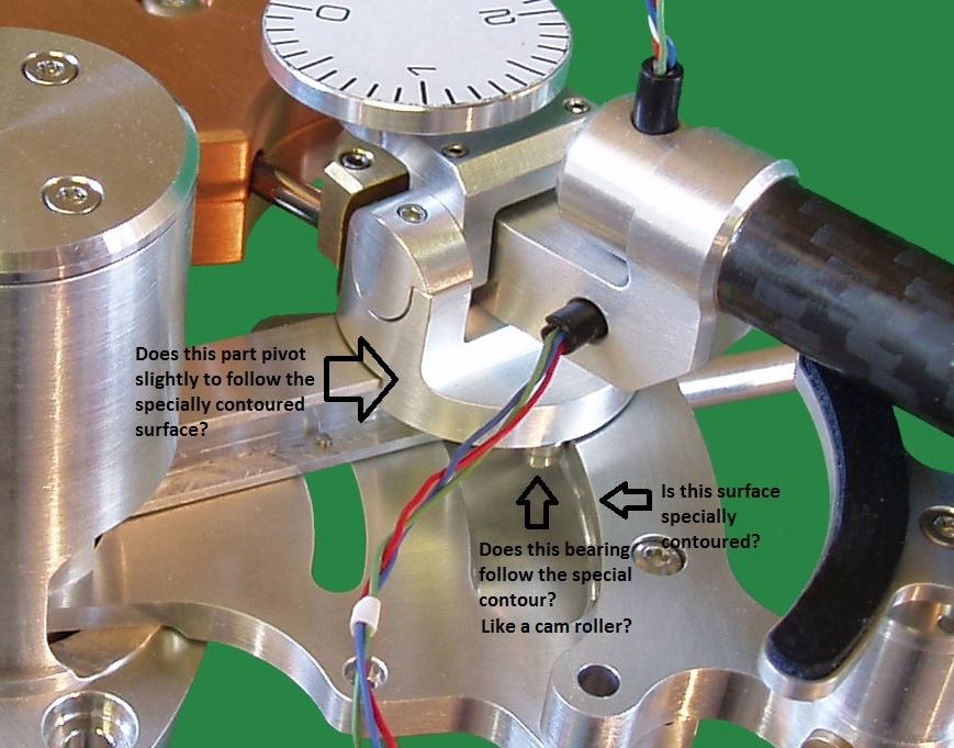
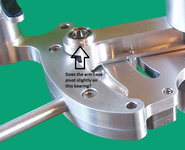
Ray K
Hello RAY K,
The answers are yes, yes, yes and yes.
Sincerely,
Ralf
My 2p worth is that I think the stylus sees no skate force. The headshell is effectively rigidly connected to the plinth. There is an internal torque within the arm structure, which is balanced at the point it connects to the plinth by a corresponding torque within the plinth.
LD
Hello luckythedog,
That's exactly right. Good show!
Sincerely,
Ralf
Thanks for the clarification, Ralf. When I said "NO" horizontal pivot in capital letter was meant to be hyperbolic. My point still stand is that the two pivot points are tied to the servo system so it does not move passively like a Birch style arm. The fixed pivot at the VTA tower AND the now clarified, existing pivot underneath the vertical arm base, work in tandem with the active servo to position the cradle to allow the headshell to "float" and track tangentially. Think of the whole assembly as a positioning robotic arm to allow linear tracking. The headshell is the real tonearm!
Just by eye, the segments don't converge to a single point so the geometry is unlikely a Thales semi-circle. Hey, as long as all the plotting points are tangential to the spindle, who cares!
I'm glad you didn't use a 4 inch cradle as that would look really weird. Glad you preserve the aesthetic of classical pivot tonearms: one of life's pleasures is dropping the needle with a fingerlift on a turntable.... and I have steady hands. Perhaps you can add that as a final touch?")
Thanks again, Carlo, for your graphic skill of providing the excellent pictures.
Putting the word separation in bold is an excellent observation. In fact it is the single most important and ingenious part of the whole design. I have never thought of applying VTF this way and preserving the VTA of a long arm but tracking tangentially with the mass of a headshell! Wicked!!
Just by eye, the segments don't converge to a single point so the geometry is unlikely a Thales semi-circle. Hey, as long as all the plotting points are tangential to the spindle, who cares!
I'm glad you didn't use a 4 inch cradle as that would look really weird. Glad you preserve the aesthetic of classical pivot tonearms: one of life's pleasures is dropping the needle with a fingerlift on a turntable.... and I have steady hands. Perhaps you can add that as a final touch?
a mini parallel linear tonearm upon a separate servo PLT base. But the winning move is the separation between the two.
Thanks again, Carlo, for your graphic skill of providing the excellent pictures.
Putting the word separation in bold is an excellent observation. In fact it is the single most important and ingenious part of the whole design. I have never thought of applying VTF this way and preserving the VTA of a long arm but tracking tangentially with the mass of a headshell! Wicked!!
Hello ThomasA,
The red lines in your drawing are not in the right place. You show the three lines converging in the wrong place. The actual horizontal tone arm pivot is located .415" (10.5mm) forward. The horizontal pivot of my tone arm is being constantly repositioned by the swinging support arm. The three red lines are not converging anywhere.
I hope this makes things a little clearer.
Sincerely,
Ralf
Yes thank you. I realized that the lines were not converging in that way but that anyway there is a force counteracted by the inertia of the servo/arm/plinth interface as LD mentions. So while the forces are there they are counteracted and skating is not present. I think I got this, I hope.
one of life's pleasures is dropping the needle with a fingerlift on a turntable... and I have steady hands. Perhaps you can add that as a final touch?
That is a good idea. The fingerlift would have to be attached to the cradle in order to prevent the head-shell from being lifted off the cradle.
Wicked!!
Hmm, if anything becomes of my tone arm, I can add your "wicked" to dtut's "devious" in future advertising
Sincerely,
Ralf
- Home
- Source & Line
- Analogue Source
- A Revolutionary Pivoting Tangential Tone Arm