Before I begin to etch my latest RIAA Pre-Amp design I just wanted some experienced peoples design knowledge on RIAA layout design.
I know that to avoid hum & microphonic noise I have to be carful around the RIAA filters but what about the rest of the circuit, I am used to etching pre amp designs fully screened but record player pre design seems a lot more sensitive maybe it's something I have not thought of.
I would like to discuss the design in detail to make sure I don't etch a fail design costing pennies per board ?
Thanks
J247W
Attachments
Last edited:
I know that to avoid hum & microphonic noise I have to be carful around the RIAA filters
but what about the rest of the circuit, I am used to etching pre amp designs fully screened
but record player pre design seems a lot more sensitive may it's something I have not thought of.
Please also post the schematic, BOM, and the top silk screen.
Have you breadboarded and tested your design yet?
Last edited:
Please also post the schematic, BOM, and the top silk screen.
Have you breadboarded and tested your design yet?
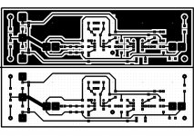
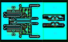
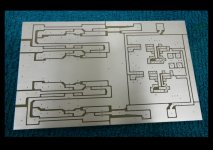
This is a single sided design & I only have the circuit diagram I made in my cad program.
This design works but needs optimising a bit more & perhaps a few tweaks ?
I want IC1 to be X6 gain & IC2 to be X10 gain to get about X60 gain overall with a MM input of 12mv X6 X10 = 720mv or less for better sig to noise ?
Regards
J247W
Attachments
Certainly AD797 is a total waste - there'll be too much noise from all those high value R's, particularly R3. The feedback network doesn't look right for RIAA. R7,8,9 are redundant.
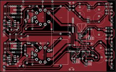
Your copper pour areas are not doing anything as they are all floating, normally they'd be connected to GND.
If I etch a board I don't usually bother with ground plane / copper pour, I always use a metal case which does a much better screening job.
If I machine a board with CNC router, then I use copper pour to save machine time and don't worry about small floating copper islands.
Is Ad797 really the best choice for a MM input?
I have used a NE5534 then replaced it with the AD797 & the treble increased in loudness & quality, so what about the OPA 134 instead ?
Please connect all your copper fills to gnd if you opt for them.
Best regards!
I do that after printing the mask, unfortunately the design program does not allow me to connect the copper screen to ground, the only other way would be to colour the circuit in with tracks but that takes ages.
Certainly AD797 is a total waste - there'll be too much noise from all those high value R's, particularly R3. The feedback network doesn't look right for RIAA. R7,8,9 are redundant.
Your copper pour areas are not doing anything as they are all floating, normally they'd be connected to GND.
If I etch a board I don't usually bother with ground plane / copper pour, I always use a metal case which does a much better screening job.
If I machine a board with CNC router, then I use copper pour to save machine time and don't worry about small floating copper islands.
When I etch I like to have minimal copper to remove to save the ferric chloride from being contaminated with too much copper to save cleaning it up / filtering the copper slag out.
As said my 3rd post my pcb design software will not connect to tracks & have to do it after
R7,8 reduce the dc offset & you need a input resistance to an op-amp to match the feedback (that's what GCSE Electronics taught me?)
Treble increased in loudness? That's not right. FR should not change. The reason for the question is that current noise is critical for MM and in that respect the 5534 takes some serious beating.
I wish I could send you a copy of the minidisk I made of the changes from before recording & after change to AD, faster slew rate op-amps always give you better treble less distortion, symbols, not sloshsy symbols of the ne5532 (from what I heard between the 2 recording I made, I mean - not in general)...
The AD's sound more like my John Lyndsay Hood transistor RIAA Pre-Amp with the AD chips ?
But anyway I am not too concerned about which op-amps I use & the RIAA filter is the same values as my JLH RIAA filter except I added the 100k down to 20k to easily change the gain needed, may use a 100k 22-turn pot to ground yet to balance the output out.
Last edited:
i always fill the rest of the pcb with copper and connect as much as possible to the ground plane. No problems with humm.
Attachments
Last edited:
.. the RIAA filter is the same values as my JLH RIAA filter except I added the 100k down to 20k to easily change the gain needed,
I see several problems here:
A) Your RIAA filter values are not the same as the two JLH RIAA schematics I found. R6 has different value and there's a missing link between components.
B) You can't just add over 100K to the feedback network and expect it to still conform to RIAA curve, it won't. It needs to be 5K6.
C) without any additional DC blocking C's you're likely to get a large DC offset at output of 2nd opamp which will limit headroom.
As you have it, the bass will be 10dB too low and the treble 10dB too high, also some deviations in the midrange.
I would put all the 1st stage feedback network component back to the JLH values and then change/reduce the gain of the second stage as needed.
See JLH Hart preamp 2/3rds down this page:
A Paul Kemble web page - John Linsley Hood preamp designs.
and the opamp version here:
John Linsley Hood K1500 Shunt Feedback MM and MC RIAA Pickup Preamp
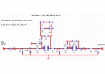
I used this circuit diagram of my owned JLH RIAA PRe-Amp
I can remove the 100k resister, but still need to lower the gain to X6 on IC1 feedback
Attachments
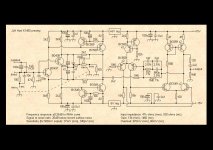
I used this circuit diagram of my owned JLH RIAA PRe-Amp
I can remove the 100k resister, but still need to lower the gain to X6 on IC1 feedback
OK, thats the same schematic as the first link in my previous post.
You can't lower the gain of 1st stage without reworking the RIAA eq network. Anyway, for x6 at 1KHz, the 20KHz gain would have to drop well below 1, but non-inverting opamp have minimum gain of 1.
Your earlier version only had x6 gain at 20KHz or so, at 1KHz it was much higher.
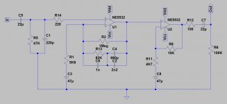
The easiest thing to do is as I said, leave the first stage like JLH and change the second stage. I've done it for you, see schematic below. I've also deleted unecessary resistors, added some caps to keep the offset under control and a few other details. The gain of this version is almost exactly x60, well x59.2 actually.
Attachments
I adjusted the gain on the original JLH by replacing both 5k6 resisters & putting 2 10k resisters in reducing the gain by half.
So this circuit I produce has a IC1 gain of X20 with the 20k resister - so how much (min) gain does the RIAA need to work ? I would prefer if IC2 was the gain IC only because I have purchased quite a few of each of the caps for the RIAA curve at those values & do not have any alternatives.
What is the minimum gain RIAA needs to work i.e X10 to change the curves or X20 ?
I know you can do this as you can make the filter passive in the circuit, IC1 is a voltage gain & IC2 is a voltage gain only too ?
The reason I want this is the lowest noise possible & the AD797 are just my recycled from an old active filter board which is redundant now - I intend to use opa134 all the way through my home built equipment, I already use the opa2134 with good results in my "ant suggested mod, Denon DRM700A"
I used to know all the calculations back in the 2000's but since then lost all my books & theory on it.
What I want is is minimum gain from the riaa filter side then pre-amp the voltage from the second IC thus making the whole circuit say X60 but gain by X10 X6 = X16 which is minimal gain the get X60 if you know what I mean ?
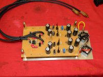
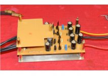
Here is some photo's of my prototype board this dual amp design is derived from & before anybody says anything I know the reg psu is too close to the RIAA...
More Thoughts...To do this properly with the gain we should use IC1 as the V gain only then put RIAA on IC2 so the filtering is happening at a higher voltage for a more efficiency just like the JLH.
Regards
J247W
So this circuit I produce has a IC1 gain of X20 with the 20k resister - so how much (min) gain does the RIAA need to work ? I would prefer if IC2 was the gain IC only because I have purchased quite a few of each of the caps for the RIAA curve at those values & do not have any alternatives.
What is the minimum gain RIAA needs to work i.e X10 to change the curves or X20 ?
I know you can do this as you can make the filter passive in the circuit, IC1 is a voltage gain & IC2 is a voltage gain only too ?
The reason I want this is the lowest noise possible & the AD797 are just my recycled from an old active filter board which is redundant now - I intend to use opa134 all the way through my home built equipment, I already use the opa2134 with good results in my "ant suggested mod, Denon DRM700A"
I used to know all the calculations back in the 2000's but since then lost all my books & theory on it.
What I want is is minimum gain from the riaa filter side then pre-amp the voltage from the second IC thus making the whole circuit say X60 but gain by X10 X6 = X16 which is minimal gain the get X60 if you know what I mean ?
Here is some photo's of my prototype board this dual amp design is derived from & before anybody says anything I know the reg psu is too close to the RIAA...
More Thoughts...To do this properly with the gain we should use IC1 as the V gain only then put RIAA on IC2 so the filtering is happening at a higher voltage for a more efficiency just like the JLH.
Regards
J247W
Attachments
Last edited:
Which changes the RIAA curve, maybe not all that much but it will change.I adjusted the gain on the original JLH by replacing both 5k6 resisters & putting 2 10k resisters in reducing the gain by half.
At least 20dB (x10) preferably more.So this circuit I produce has a IC1 gain of X20 with the 20k resister - so how much (min) gain does the RIAA need to work ?
Then there's no issue! The three RIAA eq caps, 2n2, 1n0 and 680p, are the same value in ALL of these designs, yours, mine and both JLH versions.I would prefer if IC2 was the gain IC only because I have purchased quite a few of each of the caps for the RIAA curve at those values & do not have any alternatives.
Yes, a wholly passive eq is possible but then you definitely need lots of gain in the 1st stage, otherwise the output of the filter ends up even lower level that the cartridge output, and you get more noise amplifying that back up again. If I had to do that I'd use at least +30dB gain for the first stage.What is the minimum gain RIAA needs to work i.e X10 to change the curves or X20 ?
I know you can do this as you can make the filter passive in the circuit, IC1 is a voltage gain & IC2 is a voltage gain only too ?
I don't think any of these variations talked about here are going to be SOA lowest noise. I'd start again and look at completely different designs like the OpenMM, Platina, and others I can't recall - I've seen so many.The reason I want this is the lowest noise possible & the AD797 are just my recycled from an old active filter board which is redundant now - I intend to use opa134 all the way through my home built equipment, I already use the opa2134 with good results in my "ant suggested mod, Denon DRM700A"
You should get back into it. Most of it can be found on the net if you're determined enough or get some good books and relearn it. One useful thing to do is learn how to drive LTSpice. It won't teach you how to design stuff but it's incredibly useful for testing circuits before building. Far better to reject a design on the PC than build it all up and find it was a non-starter anyway. Look through this thread RIAA calculation help needed there's some RIAA calulations in it, see if you can follow through them.I used to know all the calculations back in the 2000's but since then lost all my books & theory on it.
Not the x16 bit. I can't understand why you want this x6 low gain 1st stage. What is the perceived advantage? Any attempt to change the RIAA gain stage will need the RIAA network recalculating which will likely mean different cap values, not what you want. Most designs use a fair amount of gain in first stage for noise reasons.What I want is is minimum gain from the riaa filter side then pre-amp the voltage from the second IC thus making the whole circuit say X60 but gain by X10 X6 = X16 which is minimal gain the get X60 if you know what I mean ?
Looks like sensible parts, no wonder stuff, very good.Here is some photo's of my prototype board this dual amp design is derived from & before anybody says anything I know the reg psu is too close to the RIAA...
Yes, which is the JLH topology. Just swap the stages around. It might be worth reducing the feedback resistors of the (now 1st) flat gain stage to help reduce the noise, say 2K2 and 1K for R8 and R11 on my schematic.More Thoughts...To do this properly with the gain we should use IC1 as the V gain only then put RIAA on IC2 so the filtering is happening at a higher voltage for a more efficiency just like the JLH.
I'd still prefer more gain in the first stage. Come to think of it, why do you need 35dB gain (x60) ? it's lower than most RIAA pres which are usually more than 40dB. What cartridge are you using that has 12mV out, at 5cm/s ? Most MM carts are about 5mV.
So got the 1st stage of the circuit working on my prototype circuit after hours of finding a fault with the record player a hum like noise, went through 3 different tonearm re-wires, extra screening underneath the tonearm base.
In the end it was the new screened cable lead I had put on which has too much capacitance across it which acted like a short at the pre amp end & has been driving me nuts all weekend.
Anyway enough of my rant, here is my next question:
The op-amp based riaa pre-amp seems to be a bit dull on treble, which resister will change the treble response only leaving the bass alone as do not want to put an eq on the circuit to keep noise down ?
Regards
J247W
- Status
- This old topic is closed. If you want to reopen this topic, contact a moderator using the "Report Post" button.
- Home
- Source & Line
- Analogue Source
- RIAA - Copper fill or no copper fill?