How do you create the ideal RIAA curve? With an Formula in LTSpice or with a reveres (anti) RIAA circuit?
It's good to hear that you tune the RIAA curve in Spice. I thought I was the only one doing that and everybody else knows how to calculate them")
@Mark Thanks! That was easy to understand - even for me.
It's good to hear that you tune the RIAA curve in Spice. I thought I was the only one doing that and everybody else knows how to calculate them
@Mark Thanks! That was easy to understand - even for me.
Hi
I‘m trying to understand a specific part of rod elliott‘s project06 RIAA phono pre. Can anyone explain to me how this active Filter (r3,r4,r5,c1) is calculated?
thanks!
I'm returning to my original question regarding this circuit once again. Capacitor C2 is pictured as polar in the schematic. The Rod Elliott site says polar and non polar ca be used. Will it make any difference? Also, which voltage rating to choose for these caps. I assume 16V will be enough?
And another question: Most similar active / passive configurations don't use caps at all in this spot and seem to work just fine. Are they just for added "safety"?
The C2 is needed because most op amps have excessive input offset voltage for an RIAA circuit.
Without C2, there would be significant DC voltage at the output due to the large low frequency gain.
With C2, the gain at DC is unity, and the output DC voltage is minimized. Most RIAA circuits do
require this capacitor. A bipolar electrolytic can be used, rated for 16V or higher.
Without C2, there would be significant DC voltage at the output due to the large low frequency gain.
With C2, the gain at DC is unity, and the output DC voltage is minimized. Most RIAA circuits do
require this capacitor. A bipolar electrolytic can be used, rated for 16V or higher.
Last edited:
Still I'm surprised that most Opamp bases RIAA circuits I've seem don't use a cap in this position.
Can you list some examples? Maybe they use a servo instead.
Thanks Rayma, totally makes sense.
Still I'm surprised that most Opamp bases RIAA circuits I've seem don't use a cap in this position.
0.5mV offset x gain of 3000 = 1.5V, small compared to rails @ +/- 15V, the next coupling cap or a rumble-filter will remove this. A multi-pole rumble filter is a very good idea, so that ~10Hz can be knocked right down without impacting the bottom octave.
If using rail-to-rail opamps at 5V supply, then you'd need to address this, but standard opamp supplies will prevent clipping due to the offset unless the device has a really big ofset.
Last edited:
These circuits trade an RIAA unity gain capacitor for an output coupling capacitor.
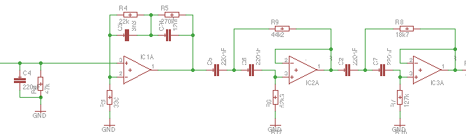
BTW if each pole and zero is created with a separate RC section, the calculations are easy, but the circuit is more convoluted:

The input opamp has 3.75k || 20nF, which is the 75µs pole. The impedances are halved to reduce noise, 7k5 || 10nF would also work.
The second opamp is a gain block only. ( sidenote: I synthesize 110µF bipolar electrolytic coupling caps - not sure how good that is, the idea is to keep them formed by biasing the midpoint through 22M resistor )
The third opamp stage has (10k + 15k + 6k8) || 10nF, which is 318µs zero, and (56k + 56k + 47k) || 20nF, which is 3.18ms pole.
All standard E12 values, only one filter capacitor value, and accuracy of response depends only on the tolerance of the passives. (Assuming one can ignore the high frequency limits of the opamp and compensation caps, and low-freq roll-off of the "bipolar" 110µF caps)
This circuit was done as an exercise in what can be done, not claiming its sensible approach (other than to avoid algebra), and it does work in real life. Note the need to protect the opamp outputs from capacitive load / ensure stability, using the 470R / 33pF networks.
The technique does allow isolated variable first-order zeros and poles if the resistors are made variable, which will be useful for something somewhere (probably).
Here is an article on Phono amp design and a spread sheet tool that uses the a Lipshitz’s methodology for all active stages (best for lowest noise and overload with opamp based designs).
I’ve had exceedingly good results with this.
RIAA Equalizer Amplifier Design
Here is another one on ‘inverse RIAA testing’
An Accurate Inverse RIAA Network
I’ve had exceedingly good results with this.
RIAA Equalizer Amplifier Design
Here is another one on ‘inverse RIAA testing’
An Accurate Inverse RIAA Network
Last edited:
Douglas Self's "Electronics for Vinyl" covers many examples and topologies of feedback network to optimize capacitor values and size for this approach, highly recommended.
Note that doing everything in one stage is convenient, tends to work quite well, but does push the opamp hard - for instance there's much less open-loop gain available with a single high-gain stage, so its quite likely my step-by-step approach is more tolerant of opamp shortcomings - so long as you boost up out of the noise in the first stage and keep impedances sensible, a multi-stage approach throws more feedback into the mix improving linearity and bandwidth (and thus reducing IM from any ultrasonic junk that's floating around). But its a lot more components - perhaps more suited to a reference circuit than practical, its trivial to invert it by swapping pole and zero sections around and make an inverse RIAA circuit, or by replacing parallel RC by series RC in each section.
Note that doing everything in one stage is convenient, tends to work quite well, but does push the opamp hard - for instance there's much less open-loop gain available with a single high-gain stage, so its quite likely my step-by-step approach is more tolerant of opamp shortcomings - so long as you boost up out of the noise in the first stage and keep impedances sensible, a multi-stage approach throws more feedback into the mix improving linearity and bandwidth (and thus reducing IM from any ultrasonic junk that's floating around). But its a lot more components - perhaps more suited to a reference circuit than practical, its trivial to invert it by swapping pole and zero sections around and make an inverse RIAA circuit, or by replacing parallel RC by series RC in each section.
A good modern opamp has an open loop gain of 10^7 at LF - more than enough to get HF distortion on an RIAA down to low ppm on a single stage design.
I get 50 ppm on an NE5532 which IMV for the 30 or 40c you pay is a fine bargain in terms of noise, distortion and overload capability.
Fact is for opamps, a single all active stage gives you the best of all worlds:- lowest noise and highest overload
I get 50 ppm on an NE5532 which IMV for the 30 or 40c you pay is a fine bargain in terms of noise, distortion and overload capability.
Fact is for opamps, a single all active stage gives you the best of all worlds:- lowest noise and highest overload
Distortion is a non issue for any competently designed electronics since the vinyl+cart+arm distortion and noise are 2 orders of magnitude worse than the electronics.
Multi-stage EQ's are definitely easier to design but half the challenge of a single all-active stage is calculating the values (I use a spread sheet) and then tweeking it on LTspice.
Multi-stage EQ's are definitely easier to design but half the challenge of a single all-active stage is calculating the values (I use a spread sheet) and then tweeking it on LTspice.
.... doing everything in one stage is convenient, tends to work quite well, but does push the opamp hard...
The opamp's open loop gain "echos" the RIAA curve only higher.
For people who think a NFB amp's OLG should be flat across the audio band, this is "perfect" because the gain-margin is very nearly flat all the way to the extremes.
For target 34dB@1kHz, a old '741 opamp has real-slim 5:1 excess gain above 2kHz, which is tons better than the bass gain-shortage of any simple discrete, but not great. And not necessary today. A '5532 has plenty of excess gain all across the audio band. There are other choices which may be better today.
That's not to detract from your very elegant step-by-step design. It sure simplifies part-ratio-matching and ordering. It does need more parts that I like to see (I'm lazy).
- Status
- This old topic is closed. If you want to reopen this topic, contact a moderator using the "Report Post" button.
- Home
- Source & Line
- Analogue Source
- RIAA calculation help needed