Hello again
just a couple of pointers
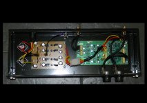
1. is that case earthed ? as it should be earthed to the star point of your psu or a earth lift resistor
2. You have the power supply cables running over the most sensitive part of the circuit, these should be screened or twisted together
3. The 5 v regulators should be installed
4. This design was designed by one of the most respected designers in the field at the time .. I would cheekily say you expect to much from your construction skills not the design
Yes a bit too cheeky!
Your hum problem is probably down to the removal of both 5V regulators , they were there to increase the smoothing on the rails that feed the more sensitive input circuitry.
My mistake , I see now on closer inspection of the photos that you have removed both on board 5V regulators and replaced them with your own off board 5V regs .My apologies to "jamesfeline" also for probably giving him a bum steer .
My mistake , I see now on closer inspection of the photos that you have removed both on board 5V regulators and replaced them with your own off board 5V regs .My apologies to "jamesfeline" also for probably giving him a bum steer .
& the rails are regulated the same as in the 5v rail comes from the output of the 15v reg to keep the same design as the circuit itself.
Ok .... sorry
was not helpful .. but points 1 to 3 are valid
Point 3 will never be valid
Thanks goes to Anthony.Taylor1967 for helping me work out the input was connected to MC input giving me the very high millvolt settings, now it has been connected to the correct inputs the voltage is now back down to -30mvac.
This has removed the deepened hiss sound from the signal to noise ratio bringing that down to the specified 26db below groove noise.
To do this I have had to strip the unit back down & also remove that darn anoying 6 pole connector which takes over 10 mins to re-connect due to it's poor design.
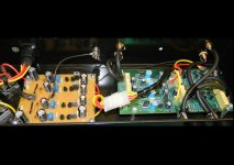
I have also re-wired the 0v to the single input point & brought it back via the phono ground lead connection then to the psu making this the single point connection. (see photos)
The +- voltage connections have all been twisted together coming back to a 4-pole connection to the psu. This is were 5vdc is taken from the 15dc reg making 5vdc a double regulation circuit just like it does on the board but with psu voltage regulation is 4 identical circuits for perfect symetry (mirror image design).
That all from me in this room of the forum, I would like to thank everyone for help/no help & the insults from people who don't look at photo's properly before going on infactual rants.
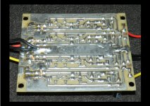
The Photo of the psu is different one but same circuit board & work just like any other psu in the world
Regards
J247W
Attachments
personally I would not use the direct coupled input option .
It appears that the direct coupled inputs and (mc) inputs are one and the same thing so now you have connected up the inputs to the AC coupled inputs AKA (mm) ie the ones with the series DC blocking capacitors.
Last edited:
Point 3 will never be valid
Thanks goes to Anthony.Taylor1967 for helping me work out the input was connected to MC input giving me the very high millvolt settings, now it has been connected to the correct inputs the voltage is now back down to -30mvac.
This has removed the deepened hiss sound from the signal to noise ratio bringing that down to the specified 26db below groove noise.
To do this I have had to strip the unit back down & also remove that darn anoying 6 pole connector which takes over 10 mins to re-connect due to it's poor design.
I have also re-wired the 0v to the single input point & brought it back via the phono ground lead connection then to the psu making this the single point connection. (see photos)
The +- voltage connections have all been twisted together coming back to a 4-pole connection to the psu. This is were 5vdc is taken from the 15dc reg making 5vdc a double regulation circuit just like it does on the board but with psu voltage regulation is 4 identical circuits for perfect symetry (mirror image design).
That all from me in this room of the forum, I would like to thank everyone for help/no help & the insults from people who don't look at photo's properly before going on infactual rants.
The Photo of the psu is different one but same circuit board & work just like any other psu in the world
Regards
J247W
in your opinion
 ... next time please do not ask for help if you do not like what you receive
 very ungrateful in my opinion ... as for spice, what is this ? some sort of drug

good riddance ...next time please do not post such a short post ... next time to suck our knowledge then just leave .. very poor in my opinion ... next time please do not ask for help if you do not like what you receive
very ungrateful in my opinion ... as for spice, what is this ? some sort of drug
people in glass houses pleases to not through stones .. feed back is a wonderful gift
... next time please do not ask for help if you do not like what you receive very ungrateful in my opinion ... as for spice, what is this ? some sort of drug
people in glass houses pleases to not through stones .. feed back is a wonderful gift
Last edited:
After point 4 how do you expect anyone to listen to what you have to say again but on that note I guess your just a Spice Software user who came straight out of school & has no experience in this field.
Really ....
 Jamesfeline. It looks like you need to take a little break. Please remain respectful or do not post.
- Status
- This old topic is closed. If you want to reopen this topic, contact a moderator using the "Report Post" button.
- Home
- Source & Line
- Analogue Source
- Gain resistors on JLH phono