Hi all, A friend on a Facebook page has seeked my help, but I can't answer. Basicall he wants to adjust the gain on a jlh phono stage. This was his original post.
This is a John Lyndsay Hood design & my circuit is exclusive to MM carts. My question is which resister would I need to adjust to turn the gain down as on my RIAA Pre-Amp it gains the output to 2vac ? TIA for any help.
This is a John Lyndsay Hood design & my circuit is exclusive to MM carts. My question is which resister would I need to adjust to turn the gain down as on my RIAA Pre-Amp it gains the output to 2vac ? TIA for any help.
Attachments

Hello epicyclic , LLPe & Anthony.taylor
I have just joined here to talk to you about my RIAA pre amp Anthony.taylor has posted for me.
I have changed the gain using 2 X 10K resistors to give me a max of 1 vrms output from as cart which reads as 12mv max vrms.
I want to replace or change the transistors for either the same ones or some higher performance transisters.
I have noticed that the BD437 & BD438 are "4 Amp" versions could I not use BD237 & BD238 instead or some other recommendations for lower noise/impedance ?
The BC559 is not as easy to get as the BC549 again is there a better pair that could be used for even lower noise ?
Also there does not seem to be a switch for MC on this board & can not find
the resisters on the pcb for the switch anyway.
Also where can I get those old large yellow caps from as modern versions would be a lot smaller, or do they do something better that I do not know about ?
Thanks for all you help so far
Jon
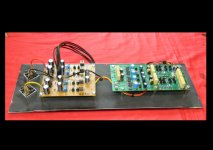

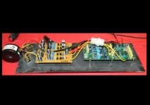
Your board may be configured for mc input , would you supply a near overhead ( to avoid flash white out ) photo of the phono board only so I/we can check component values /count . With the current photos some components are obscured and also hard to read the values of .
BD437 and 438 are chosen for there low noise performance in this application .
BD437 and 438 are chosen for there low noise performance in this application .
Your board may be configured for mc input , would you supply a near overhead ( to avoid flash white out ) photo of the phono board only so I/we can check component values /count . With the current photos some components are obscured and also hard to read the values of .
BD437 and 438 are chosen for there low noise performance in this application .
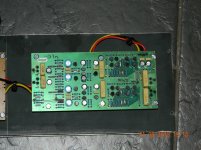
I followed the circuit diagram through & all values seem to match but I am new to the circuit, so could of missed something & I am still wondering were I could get the replacement 2u2F & 1uF caps from the same size ?
Attachments
Your board may be configured for mc input ,
Provided R1 and R31 are both 150 ohms and not shorted out under the board everything looks normal .
I am still wondering were I could get the replacement 2u2F & 1uF caps from the same size ?
I personally would not change them tho others may suggest replacement with polypropylene . If yours are marked with MKT or MKS then they are polyester , polypropylene are MKP marked . Have you looked in Farnell .
Ps............. Vinylengine have the construction manual and brochure (flyer) for download but you will need to login .
Last edited:
Provided R1 and R31 are both 150 ohms and not shorted out under the board everything looks normal .
My mistake I should have typed R10 and R40
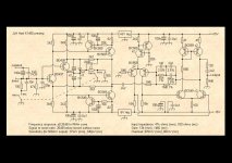
I have been poring over the gain structure of this RIAA pre amp this morning (I must get a life) and I am confident that I have found a typing error on the below schematic .
On the bottom left it states mm sensitivity of 37mV this should read 3.7mV.
If you look at the bottom right it says the mm gain is 134 which is correct 500mv/134 =3.73mV.
Gain structure... first stage mm 18.16dB
.......................first stage mc 39.33dB
.......................second stage (RIAA) 24dB @ 1Khz
Attachments
Last edited:
I also doubt the "340pV (mc)"; 340 uV (micro) is more likely.
Yes agreed .................. I missed that . My excuse is I have been concentrating on the bogus 37mV mm sensitivity .
mc ... 340uV....... 0.000340x1460=0.496V

Last edited:
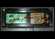
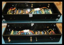
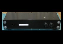
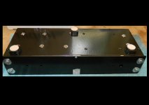
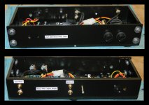
As in photos you will see the rebuild complete.
The only problem with this RIAA Pre now is the background noise which may be caused by the following information:
Left Channel Input Voltage (not connected to r/p leads) -127mv
Right Channel Input Voltage (not connected to r/p leads) -281mv
With my prototype op-amp based riaa I get a high gain hiss if you turn the volume up like all other riaa pre's I have had well below groove noise.
Now with the JLH I get a deep humming sound, below groove noise but higher than the prototype op-amp based one but still lower than the groove noise, you can feel the hum on headphones if you know what I mean.
Please no fixing advise on earthing as earthing is perfect with no noise.
Could the dc offsets on the inputs be causing this deep rumbling noise & what silicon should I change everything or just the bd's ?
Regards
J247W
Attachments
-
 JLH RIAA PreAmp 004.jpg639.9 KB · Views: 148
 -
 JLH RIAA PreAmp 003.jpg736 KB · Views: 140
 -
 JLH RIAA PreAmp 002.jpg510.8 KB · Views: 155
 -
 JLH RIAA PreAmp 001.jpg528.2 KB · Views: 147
 -
 JLH RIAA PreAmp 007.jpg692.9 KB · Views: 61
 -
 JLH RIAA PreAmp 008.jpg373.1 KB · Views: 45
 -
 JLH RIAA PreAmp 005.jpg434.4 KB · Views: 68
 -
 JLH RIAA PreAmp 006.jpg640.5 KB · Views: 62
Your hum problem is probably down to the removal of both 5V regulators , they were there to increase the smoothing on the rails that feed the more sensitive input circuitry. Those voltages at the inputs are about correct , personally I would not use the direct coupled input option .
Your hum problem is probably down to the removal of both 5V regulators , they were there to increase the smoothing on the rails that feed the more sensitive input circuitry. Those voltages at the inputs are about correct , personally I would not use the direct coupled input option .
I have been making regulated power supplys for many years so I doubt your answer about the "more precise" +-5Vdc supply rails as they are symetrical voltages being given to the circuit (+-15v & +-5v) not just a "thrown together" Hart psu with way out "plus" to "minus" voltage of up to 2vdc differences
I was thinking the fault is more to do with the ac offsets at the input making the signal to noise hum instead of hiss, my prototype op-amp version is only giving -15mv on each input measured (Fluke MM).
On the other hand a JLH pre-amp is not all it is cracked up to be (people tend to go on about them as "all singing & all dancing") but I have heard Linn systems, "so called" high end equipment & the price they pay does not warrant the hefty price tag & the circuits inside are not different to anything you have seen.
Maybee I expected too much from this design ?
Hello
The 5v regulators are there for a reason .. also just for info my JLH phono preamp with the Hart PSU does not hum at works faultlessly, as I have a original unit.
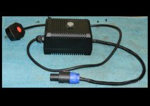
You need to retry with the 5V regulators for the front end .. the fact that mine works and yours has a issue there must be a mistake at some area in your work .. just my humble opinion of course .. post up some more pics of your power supply that you have used for a second opinion
Also note the Hart supply has a good star grounding pcb tracks and a good earth lift circuit that actually works ..
all the best
The 5v regulators are there for a reason .. also just for info my JLH phono preamp with the Hart PSU does not hum at works faultlessly, as I have a original unit.
You need to retry with the 5V regulators for the front end .. the fact that mine works and yours has a issue there must be a mistake at some area in your work .. just my humble opinion of course .. post up some more pics of your power supply that you have used for a second opinion
Also note the Hart supply has a good star grounding pcb tracks and a good earth lift circuit that actually works ..
all the best
Hello again
just a couple of pointers
1. is that case earthed ? as it should be earthed to the star point of your psu or a earth lift resistor
2. You have the power supply cables running over the most sensitive part of the circuit, these should be screened or twisted together
3. The 5 v regulators should be installed
4. This design was designed by one of the most respected designers in the field at the time .. I would cheekily say you expect to much from your construction skills not the design
Hello again
just a couple of pointers
1. is that case earthed ? as it should be earthed to the star point of your psu or a earth lift resistor
2. You have the power supply cables running over the most sensitive part of the circuit, these should be screened or twisted together
3. The 5 v regulators should be installed
4. This design was designed by one of the most respected designers in the field at the time .. I would cheekily say you expect to much from your construction skills not the design
After point 4 how do you expect anyone to listen to what you have to say again but on that note I guess your just a Spice Software user who came straight out of school & has no experience in this field.
- Status
- This old topic is closed. If you want to reopen this topic, contact a moderator using the "Report Post" button.
- Home
- Source & Line
- Analogue Source
- Gain resistors on JLH phono