Hello Folks!
I am looking for expert help trying to decipher some of the service manual alignment set points for my Kenwood tuners. I did take my electronic course many moons ago and have been going through some of my literature but I am still having issues in some areas as I have never done an alignment but am more than confident that I can figure it out, I'm just having a little trouble getting out of the gate!
I have 4 Kenwood tuner/receivers that I refurbished but am now at the stage where I would like to check and align the tuner section if required. I have all 4 service manuals, volt meters, a 60 Mhz scope...Yes, I know that it's not enough for FM alignment but I have a new 200 Mhz scope on it's way and should be here Friday. I also acquired a Jung Jin JSG-1101B FM/AM Stereo Signal Generator which I believe to be a Kenwood SG-5110. Both units appear to be identical and spent last weekend familiarizing myself with it's operation. It's output can be selected at dBu EMF or dBm. And yes, I did construct an impedance matching pad so I'm good to go. I also have a distortion analyzer.
The 4 units are....
Kenwood Model Eleven GX..........I LOVE this unit! The sound is so crisp and has a very warm natural sound to it!
Kenwood KT-3300d
Kenwood KT-5020
Kenwood KRC-939 ........Automobile Deck
The first thing that I would like to point out is that I don't understand why the manufacturers can't keep things simple and use actual voltages instead of using dB, dBu EMF, dBm or any other forms. All this just adds to the confusion. It is my understanding that Japan manufactures used dBu EMF but none of my manuals make reference to that. I have also been using this web site for conversions...... https://www.eeweb.com/tools/rf-unit-converter ......but without knowing for sure what they are actually using in the service manual, it complicates things a little.
My vintage Model Eleven GX from the late 70's uses dB (ANT INPUT) and makes reference in the manual that 0 dB = 1 uV.
My KT-3300d and KT-5020 from the late 80's both use dBu (ANT INPUT) with no reference.
My KRC-939 from the late 80's uses dB (ANT INPUT) with no reference.
As you can see, there is no consistency from one unit to the next as far as input levels go which is confusing.
So now let's move on to the actual alignment. This will be for the KRC-939. I have a spare unit that I marked all the pots with a fine tip marker so that I can go back in the event I screw up. I'm using this deck as a practice unit.
The first adjustment is discriminator.... input setting 98.1 Mhz, 0 dev, 60dB (ANT INPUT)......output setting DC volt meter across TP6........Tuner setting 98.1 Mhz and align T3 for 0 volt.
I had no problem getting this completed and it was very close already.
The next adjustment is Stop Level..... input setting 98.1 Mhz, 0 dev, 20dB (ANT INPUT) .....no output setting, was left blank.......Tuner setting 98.1 Mhz and adjust VR6 for Stop.
What the hell is Stop Level? I tried adjusting this pot but did not see anything change on anything.
My KT-5020 also has this alignment and says align .......To the position so that the lowest level of the S meter lights.
Next adjustment is Distortion.........input setting 98.1 Mhz, 75khz dev, 60 dB (ANT INPUT).........no output setting, was left blank.......Tuner Setting 98.1 Mhz and adjust VR9 for minimum distortion.
How am I suppose to read the distortion level? My service manual makes no metion of a distortion meter, only a volt meter and a scope on the output across speaker.
Next adjustment is Pilot Canceler........input setting 98.1 Mhz, 0 dev, Pilot : On, 60 dB (ANT INPUT)........Output Setting is Volt Meter and Scope.......Tuner setting 98.1 Mhz and adjust VR10 for minimum output.
Once again, I could not see any change on the scope as I adjusted this pot. Of course I was using my 60 Mhz scope and perhaps I need to try again with my new 200 Mhz scope once it arrives on Friday
Next adjustment is Separation.........input setting 98.1 Mhz, 1Khz +or- 68.25 Khz dev , Selector L or R, Pilot : +or- 6.75 Khz dev, 60 dB (ANT INPUT).......output setting is Volt meter and Scope.........tuner setting is 98.1 Mhz and adjust VR11 for minimum crosstalk.
I'm not sure about the Pilot : +or- 6.75 Khz dev part as far as setting my generator for this.
There are a couple more adjustments that need to be checked but we can start with this as I believe that once I figure these out with some help, the rest will all fall into place, at least I hope!
I really hope that once I get my new scope that I will be able to see what I'm suppose to be looking for cause right now I have no idea what the output is suppose to look like.
If there are any experienced tuner experts here, then I would be very grateful for any help that I can get!
Thanks!
Roland
Attachments
Last edited:
For all four units 0dB=1uV (dBu). Then 20dB=10uV and 60dB=1000uV.
Stop level is probably the minimum signal level to stop an autoscan of the band.
Distortion is measured on a THD meter or spectrum analyzer. Gross distortion can be seen on an oscilloscope. Leave this adjustment alone if you do not have equipment to measure distortion.
Pilot canceller is a 19kHz notch filter to remove the pilot signal from the output. There is always some residual 19kHz pilot signal left in the audio output but it should be quite small when the filter is adjusted properly.
Generator pilot deviation should be 9% of the total 75kHz deviation of the test signal from what you posted. Does the generator have a way to adjust the pilot amplitude (deviation)?
A 60MHz scope should be quite adequate for the adjustments you asked about.
The first thing that I would like to point out is that I don't understand why the manufacturers can't keep things simple and use actual voltages instead of using dB, dBu EMF, dBm or any other forms.
At least for FM car radios, dBuV EMF is pretty standard nowadays. Silly, because almost any non-broadcast receiver uses dBm - which gives you more meaningful results when you compare receivers meant for different antenna (aerial) impedances.
The first adjustment is discriminator.... input setting 98.1 Mhz, 0 dev, 60dB (ANT INPUT)......output setting DC volt meter across TP6........Tuner setting 98.1 Mhz and align T3 for 0 volt.
I had no problem getting this completed and it was very close already.
OK, so far so good!
The next adjustment is Stop Level..... input setting 98.1 Mhz, 0 dev, 20dB (ANT INPUT) .....no output setting, was left blank.......Tuner setting 98.1 Mhz and adjust VR6 for Stop.
What the hell is Stop Level? I tried adjusting this pot but did not see anything change on anything.
Is there an automatic transmitter searching function? If so, then this is probably the minimum level at which it stops searching.
Next adjustment is Distortion.........input setting 98.1 Mhz, 75khz dev, 60 dB (ANT INPUT).........no output setting, was left blank.......Tuner Setting 98.1 Mhz and adjust VR9 for minimum distortion.
How am I suppose to read the distortion level? My service manual makes no metion of a distortion meter, only a volt meter and a scope on the output across speaker.
Yes, for this one you need a distortion meter (or very good ears).
Next adjustment is Pilot Canceler........input setting 98.1 Mhz, 0 dev, Pilot : On, 60 dB (ANT INPUT)........Output Setting is Volt Meter and Scope.......Tuner setting 98.1 Mhz and adjust VR10 for minimum output.
Once again, I could not see any change on the scope as I adjusted this pot. Of course I was using my 60 Mhz scope and perhaps I need to try again with my new 200 Mhz scope once it arrives on Friday
What you are looking for and trying to minimize, are 19 kHz residues on the audio outputs. You don't need a 200 MHz scope for that, in fact, the smaller the bandwidth, the less the 19 kHz residue is obscured by the scope's noise.
Next adjustment is Separation.........input setting 98.1 Mhz, 1Khz +or- 68.25 Khz dev , Selector L or R, Pilot : +or- 6.75 Khz dev, 60 dB (ANT INPUT).......output setting is Volt meter and Scope.........tuner setting is 98.1 Mhz and adjust VR11 for minimum crosstalk.
I'm not sure about the Pilot : +or- 6.75 Khz dev part as far as setting my generator for this.
6.75 kHz peak deviation is the nominal level for an FM pilot tone. If your generator doesn't allow you to adjust it, it is probably 6.75 kHz by default. In any case, unless there is something very wrong with the radio, any level between 6 kHz and 7.5 kHz peak deviation should give essentially the same result.
Instead of playing a 1 kHz tone through one channel (left, for example) of the signal generator and adjusting for minimum signal at the other channel (right) of the receiver, you could also play your favourite music through the left channel of the signal generator and adjust by ear for minimum audio on the right channel receiver output. That makes the adjustment more meaningful for normal audio. (This is assuming that there is only one adjustment for channel separation, not several that need to be done with different modulation frequencies.)
Last edited:
I have not done it in years, but I used to align directly from the schematic trying to figure out (usually easy) exactly what each trim does. The distortion can be trimmed pretty well by eye if you have an FM sweep generator in the 100Mhz range. You trim the detector slope to be as symmetrical as possible and as straight as possible through 0. Never had any fancy instruments.
There are some ham techniques online for optimizing the front end if you need to do that.
There are some ham techniques online for optimizing the front end if you need to do that.
For all four units 0dB=1uV (dBu). Then 20dB=10uV and 60dB=1000uV.
I would would be nice if that was the actual reference. Still makes me wonder why Kenwood would make a FM Stereo generator to align tuners using dBu EMF or dBm as an output selection but yet use dBu=1uV as a reference in their own service manual. The dBu=1uV was only referenced in the manual for the Model Eleven GX which was a model from the late 70's and the other models are from the late 80's.
For all four units 0dB=1uV (dBu). Then 20dB=10uV and 60dB=1000uV.
Stop level is probably the minimum signal level to stop an autoscan of the band
Distortion is measured on a THD meter or spectrum analyzer. Gross distortion can be seen on an oscilloscope. Leave this adjustment alone if you do not have equipment to measure distortion.
Pilot canceller is a 19kHz notch filter to remove the pilot signal from the output. There is always some residual 19kHz pilot signal left in the audio output but it should be quite small when the filter is adjusted properly.
Generator pilot deviation should be 9% of the total 75kHz deviation of the test signal from what you posted. Does the generator have a way to adjust the pilot amplitude (deviation)?
A 60MHz scope should be quite adequate for the adjustments you asked about.
Stop level sounds right.
As far as distortion goes, I do have a distortion analyzer but the service manual makes no mention of how or where to connect so I'm a little unsure about this.
My generator does allow to set the Pilot level from 0-15%
Is 9% the norm?
The manual does not mention what % level to set the Pilot
dBu is shorthand for dB with respect to 1uV. dB is always a relative quantity and all your tuners are referenced the same.
The distortion meter would connect to the tuner audio output. Hopefully in the case of the car stereo, the power amplifier does not swamp the tuner distortion. If it does, measure further back in the audio chain like at the volume control.
Pilot levels between 8 and 10% are normal.
The distortion meter would connect to the tuner audio output. Hopefully in the case of the car stereo, the power amplifier does not swamp the tuner distortion. If it does, measure further back in the audio chain like at the volume control.
Pilot levels between 8 and 10% are normal.
Is there an automatic transmitter searching function? If so, then this is probably the minimum level at which it stops searching.
Yes there is so thats probably correct
Yes, for this one you need a distortion meter (or very good ears).
I do have a distortion analyzer but the manual makes no reference of one being used for the adjustment or does it even mention one other than a volt meter and a scope.
What you are looking for and trying to minimize, are 19 kHz residues on the audio outputs. You don't need a 200 MHz scope for that, in fact, the smaller the bandwidth, the less the 19 kHz residue is obscured by the scope's noise.
I'm not sure what I'm suppose to be looking for on the scope. I noticed no change on my scope when I tried to adjust. I should have seen something different.
6.75 kHz peak deviation is the nominal level for an FM pilot tone. If your generator doesn't allow you to adjust it, it is probably 6.75 kHz by default. In any case, unless there is something very wrong with the radio, any level between 6 kHz and 7.5 kHz peak deviation should give essentially the same result.
Ok, now I get it! My generator displays it in percentage so 9% level setting on my generator is the same as 6.75khz
9% of 75 khz = 6.75 khz
Instead of playing a 1 kHz tone through one channel (left, for example) of the signal generator and adjusting for minimum signal at the other channel (right) of the receiver, you could also play your favourite music through the left channel of the signal generator and adjust by ear for minimum audio on the right channel receiver output. That makes the adjustment more meaningful for normal audio. (This is assuming that there is only one adjustment for channel separation, not several that need to be done with different modulation frequencies.)
That's a good idea! So I can use the left or right external input connections to feed a signal into the generator like my distortion analyzer for example?
I do have a distortion analyzer but the manual makes no reference of one being used for the adjustment or does it even mention one other than a volt meter and a scope.
It's silly that they forgot to mention that you need one, but anyway, as Bill already wrote, its input has to be connected to an audio output of the tuner. The signal generator has to be modulated with a low-distortion sine wave.
I'm not sure what I'm suppose to be looking for on the scope. I noticed no change on my scope when I tried to adjust. I should have seen something different.
When the pilot tone of the signal generator is on, but otherwise there's no modulation, you should see a very small 19 kHz signal at the audio outputs of your tuner. If you don't, I have no idea why not. By the way, the pilot level for this adjustment has to be precisely 9 %.
Do you use a 1:1 passive probe, with the scope set to 1 Mohm input resistance and limited bandwidth? Can you maybe use your distortion analyser as a selective voltmeter?
Ok, now I get it! My generator displays it in percentage so 9% level setting on my generator is the same as 6.75khz
9% of 75 khz = 6.75 khz
Exactly!
That's a good idea! So I can use the left or right external input connections to feed a signal into the generator like my distortion analyzer for example?
I don't know your FM stereo signal generator, but usually you can feed in an external modulating signal.
Last edited:
Thanks to all you guy's so far! This info has helped a lot!
My distortion meter/analyzer has an output and input feed and my generator has a left and a right external input feed and an output.
I was not aware that in order to use a distortion meter, that I would need to feed a an output from the distortion meter, into the signal generator, through the tuner and then back to the input of the distortion meter.
Is this how all distortion meters work? Or are there some distortion meters that only require an input from the source to detect the distortion level???
dBu is shorthand for dB with respect to 1uV. dB is always a relative quantity and all your tuners are referenced the same.
The distortion meter would connect to the tuner audio output. Hopefully in the case of the car stereo, the power amplifier does not swamp the tuner distortion. If it does, measure further back in the audio chain like at the volume control.
Pilot levels between 8 and 10% are normal.
i'm not using a power amp. I have my connection directly on the audio out RCA's of the tuner.
It seems a Pilot level of 9% is the correct number that I need.
")
......are there some distortion meters that only require an input from the source to detect the distortion level???
That can work.
But what is this "source"? A low-price FM generator may have a 7-cent audio oscillator with 5% THD, and maybe at 876Hz instead of 1KHz.
Yes, you can detect distortion by taking *both* the raw source and the "received" signal. But if the source distortion is not small, uncertainties pile up.
The Usual Way To Measure Distortion is to put a low-THD oscillator to the Unit Under Test and analyze the output. The oscillator and analyzer may be sold together, or separate, even different makes as long as they are good.
The only difference here is that your Unit Under Test is necessarily an audio-to-FM converter and an FM-to-audio receiver, together. And the two THDs do combine. So until the FM Generator is certified low-THD, you can't get the true THD of the receiver alone. However in this case you just want *lowest* THD as you turn a slug in the receiver. While a high-THD FM-Gen would mask the depth of the lowest THD, you will also rock around that point to see where THD come up. Split the difference and that really should be "optimum", or so close you'll never mind. (If the THD-vs-slug relation is very asymmetrical, something is broke.)
_I_ think these meter-tests are for first set-up, and for when the repair tech must work in a steel cellar. Particularly STOP.... put it on your usual antenna and hit Scan. If Stop is too low, it stops at any slight noise. If too high, it never stops, or only for a tower you can see from your window. The "ideal" setting is so it gets all your usable signals and skips most of the too-weak and just-noise channels. Likewise Distortion "can" be trimmed by tuning a good signal, really centered, then rocking the slug until signal garbles, back until it garbles again, and centering the slub between those two limits.
Last edited:
If the FM signal generator has a distortion in the same order as the receiver or worse, the whole distortion trimming procedure becomes dubious, because minimum distortion may then mean that the receiver's distortion cancels as much as possible of the FM signal generator's distortion.
That can work.
But what is this "source"? A low-price FM generator may have a 7-cent audio oscillator with 5% THD, and maybe at 876Hz instead of 1KHz.
Yes, you can detect distortion by taking *both* the raw source and the "received" signal. But if the source distortion is not small, uncertainties pile up.
The Usual Way To Measure Distortion is to put a low-THD oscillator to the Unit Under Test and analyze the output. The oscillator and analyzer may be sold together, or separate, even different makes as long as they are good.
Ok, this is what I have......
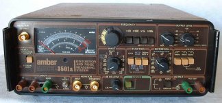
Amber 3501 distortion and noise analyzer from 1988.
internal oscillator output 10 Hz to 50 khz .003% THD
50 Hz to 5 Khz .0008% THD
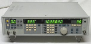
Kenwood SG-5110 Am/Fm stereo generator
Distortion Factor 0.05% or less (RF: 10.7Mhz, 76 Mhz - 110Mhz )
Could I just simply use the 1Khz or 400 Hz modulated frequency of the generator and hook the distortion meter at the rca output of the tuner to check distortion?
Or should I use the use the internal oscillator of the distortion meter, feed into the external input of the generator and then check the distortion with the input of the distortion meter connected to the rca output of the tuner?
The only difference here is that your Unit Under Test is necessarily an audio-to-FM converter and an FM-to-audio receiver, together. And the two THDs do combine. So until the FM Generator is certified low-THD, you can't get the true THD of the receiver alone. However in this case you just want *lowest* THD as you turn a slug in the receiver. While a high-THD FM-Gen would mask the depth of the lowest THD, you will also rock around that point to see where THD come up. Split the difference and that really should be "optimum", or so close you'll never mind. (If the THD-vs-slug relation is very asymmetrical, something is broke.)
That make sense to me....
Attachments
Last edited:
If the FM signal generator has a distortion in the same order as the receiver or worse, the whole distortion trimming procedure becomes dubious, because minimum distortion may then mean that the receiver's distortion cancels as much as possible of the FM signal generator's distortion.
That makes total sense to me!!
My guess would be that the distortion trimming becomes somewhat more accurate when you use the distortion analyzer's oscillator. I can't say by how much, though, because Kenwood doesn't specify how much of the 0.05 % distortion comes from their VCO and how much from their low-frequency oscillator.
I had some good luck today!
Played around with my distortion meter and my new scope. After several hours of getting to know both of these units, I was finally able to figure out how to check and adjust my distortion level. The tuner was actually close but was able to tweak it a little better.
My Amber distortion meter works like a charm and has some really nice features and some awesome specs!. Was well worth the money, although I did not spend much for it!
Now I just need to pick up some extra bnc cables and continue experimenting till I can do this with my eyes closed!
I also discovered another issue when following the service manual adjustment procedure.
The manual says to set my generator for 98.1 Mhz and set tuner for 98.1 Mhz for most of the procedures.
What am I suppose to do if I have a strong station at 98.2 Mhz spilling over, affecting my readings?
Is there a reason why it has to be 98.1Mhz? Can I set my generator for 97.7 and set tuner for the same and do my adjustments at that frequency?
Last edited:
- Status
- This old topic is closed. If you want to reopen this topic, contact a moderator using the "Report Post" button.
- Home
- Source & Line
- Analogue Source
- I need help with FM Tuner alignment