This topic came up in a chat about a specific phono preamp, but is NOT limited to any single design. IMHO it touches things that should be known, or knowable, by most folks on a DIY audio forum.
Let's review Fundamentals.
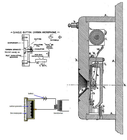
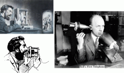
Alex Bell invented devices to turn speech sound into electricity and electricity to sound. It worked enough to get funding. It did not work very well.
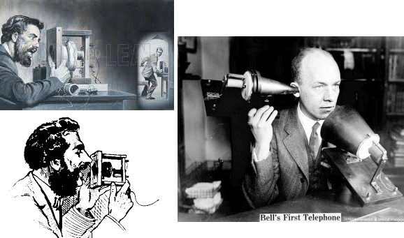
A number of reasons, starting with the fact that converting vibrations of thin air to vibrations of electrons, or back, is always very lossy. What you get out is much-much less than you put in. The system really needed an Amplifier. Something to take a small interesting signal, and a strong boring current (battery), and make a large interesting signal.
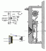
The carbon mike filled this need for almost 100 years.
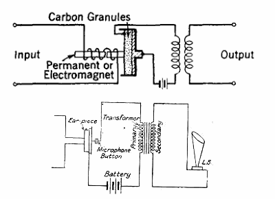
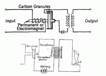
This worked cross-town. Long lines have more loss. The obvious hack is to put an earpiece against a carbon mike to amplify the signal.
LINK: Doug Self on Mechanical Amplifiers
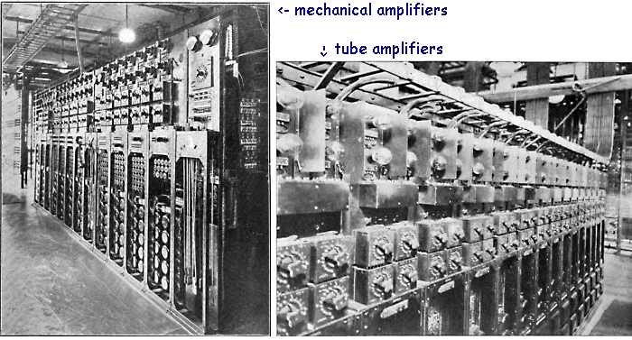
However the carbon mike is a nasty thing, and a cascode of carbon amplifiers is pretty bad.
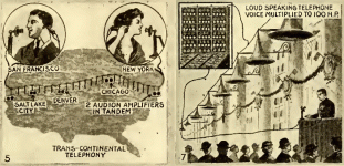
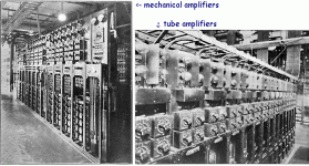
Carbon mechanical amplifiers were soon replaced with Audion thermionic (tube) amplifiers.
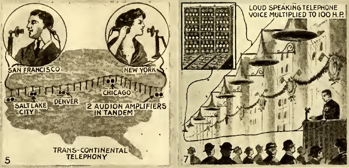
No amplifier can make "infinite" output. They all have a limit how much output they can deliver. The carbon mike can not output more than what its battery can give (and really much less). Amplifiers of all types have similar limits.
But electronics audio signals are invisible. Let's try pictures.
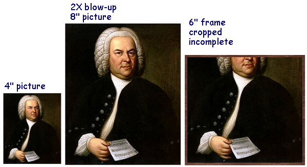
You have an image 4 inches high. You blow it up 2X. Now it is 8 inches high, bigger, good. But say you have to fit it in a 6 inch frame. You lose important detail. "Clipping".
To avoid clipping, we must: know our maximum input level, know our overload level, and set gain so the max input does not reach clipping.
In general, we do not know input level with precision. Some leeway must be allowed. Yes, a big modern exception is Digital Audio. The DAC chip has an Absolute Maximum that it can output for an All-Ones signal, Digital Full Scale. Tape has a soft limit. Phono record cutters are capable of incredibly high groove levels. But you can not fit a lot of wide grooves on a phono-disc. Phono is a compromise between playing-time and recorded level. We can be sure an 18 minute side will be only so-loud. Some Disco Singles are cut very much louder.
We also have various types of overload. Old no-NFB amplifiers got "sour" before they hard-clipped. We might allow one 5% THD stage in a chain. But broadcast networks and mature recordings systems had dozens of amplifiers in cascade. The usual thing was to build an amp good for 10 Watts at few-% THD, then rate it for 1 Watt, where THD might be 0.1% and several in cascade would not sound bad. "Headroom". OTOH modern high-NFB amps have low-low THD right to the edge of clipping, and we can work them with little "headroom".
So what is the output of a phono cartridge? Stick with MM for now, MC is a minor difference.
The number on the spec-sheet is usually about "5mV@1KHz" (3mV-9mV). But this is for a test calibration level which is below the maximum a cutter can cut. I will assert, without proof here, that peaks to +16dB happen, which makes 30mV@1KHz.
If we design a phono preamp for 40dB (1:100) gain @1KHz, and put in 30mV (0.030V), then we get 3V output. About 4.2V peak, hardly 9V peak to peak. This conclusion is supported by many phono preamps which work "mostly OK" with 12V supply, though not always with full 40dB gain.
If it was just that simple, we'd pick a somewhat higher supply voltage just in case, and be done with it. So what is Doug Self talking about??
Now we throw some curve-balls. While 1Khz is a handy mid-band measuring point, audio covers more than 50Hz-15KHz. And the modern (since 1951) phono cartridge has a strongly rising frequency response. If we feed it a constant-width groove-wiggle, output doubles every octave, 20dB per decade, 60dB over 20Hz-20KHz. To get back to a "flat" response we have to put a heavy bass boost treble cut on the signal.
If we assume 1:100 or 40dB gain at 1KHz we actually mean:
- 1,000 (60dB) @ 50Hz
--- 100 (40dB) @ 1KHz
---- 10 (20dB) @ 20KHz
That is a -wide- range of gain.
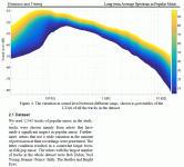
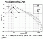
While the small-signal response should be flat, the overload problem has a different frequency curve. No normal sound has big power above 1KHz; no human ear wants to hear huge power in the top of the audio range. Traditional music fills 150Hz-1KHz more or less, with smaller harmonics. Modern musical productions have boosted treble some, and bass a lot.
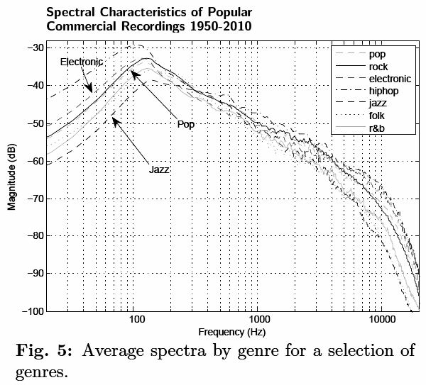
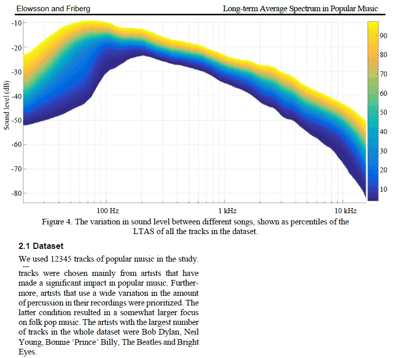
The Pestana and Elowsson data agree closely.
If we put these curves through an inverse-RIAA filter, this is what goes into the phono preamp. Preamp gain is different at every frequency, so we need to do a bunch of computation.
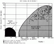
Actually, Shure did a survey of groove levels in 1973.
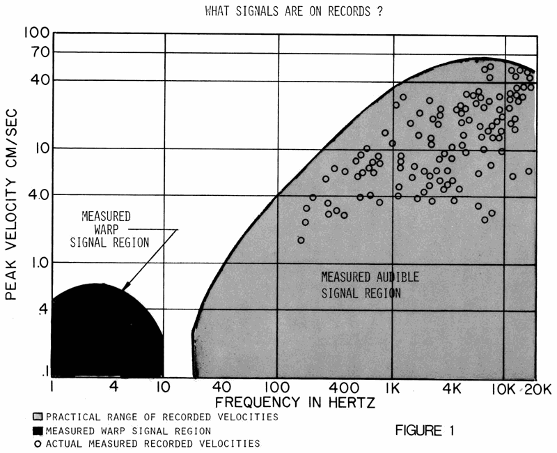
This is mostly a 6dB/oct rise 50dB to 1KHz and flatening out above 1KHz. If rotated 45 degrees to cancel the 6dB slant, 10KHz is about 12dB below 1KHz. This does not disagree with the final spectras shown above.
Convert the Shure cm/Sec curve to voltage; a first-crack is to assume 1mV/(cm/Sec) so the mV scale runs from 0.1mV to 100mV. Multiply this against preamp gain. Check against overload.
For the "single" (RIAA NFB loop) preamp, we need only check at the final output.
The "passive" plan with alternate gain and lossy EQ, we must check at every stage.
FWIW: the "passive" plan "needs" multiple amplifier stages. If we passive-EQ first then gain-up, the input to the amplifier becomes far too weak to compete with universal hiss. If we amplify first then passive EQ, the amplifier has to deliver over 70 Volts, and the output of the passive EQ may be the right voltage but with too little current to drive the next box (or the first stage has to be BIG power to drive a low-Z passive EQ's loss). Two stages is of course better, and some tube plans do "OK", but still difficult to do well. Hagerman knew what he was doing when he grabbed three amplifiers.
various said:...phono preamp has bad overload...
...how to compute the overload margin...
...for various frequencies?...
Let's review Fundamentals.
Alex Bell invented devices to turn speech sound into electricity and electricity to sound. It worked enough to get funding. It did not work very well.
A number of reasons, starting with the fact that converting vibrations of thin air to vibrations of electrons, or back, is always very lossy. What you get out is much-much less than you put in. The system really needed an Amplifier. Something to take a small interesting signal, and a strong boring current (battery), and make a large interesting signal.
The carbon mike filled this need for almost 100 years.
This worked cross-town. Long lines have more loss. The obvious hack is to put an earpiece against a carbon mike to amplify the signal.
LINK: Doug Self on Mechanical Amplifiers
However the carbon mike is a nasty thing, and a cascode of carbon amplifiers is pretty bad.
Carbon mechanical amplifiers were soon replaced with Audion thermionic (tube) amplifiers.
No amplifier can make "infinite" output. They all have a limit how much output they can deliver. The carbon mike can not output more than what its battery can give (and really much less). Amplifiers of all types have similar limits.
But electronics audio signals are invisible. Let's try pictures.
You have an image 4 inches high. You blow it up 2X. Now it is 8 inches high, bigger, good. But say you have to fit it in a 6 inch frame. You lose important detail. "Clipping".
To avoid clipping, we must: know our maximum input level, know our overload level, and set gain so the max input does not reach clipping.
In general, we do not know input level with precision. Some leeway must be allowed. Yes, a big modern exception is Digital Audio. The DAC chip has an Absolute Maximum that it can output for an All-Ones signal, Digital Full Scale. Tape has a soft limit. Phono record cutters are capable of incredibly high groove levels. But you can not fit a lot of wide grooves on a phono-disc. Phono is a compromise between playing-time and recorded level. We can be sure an 18 minute side will be only so-loud. Some Disco Singles are cut very much louder.
We also have various types of overload. Old no-NFB amplifiers got "sour" before they hard-clipped. We might allow one 5% THD stage in a chain. But broadcast networks and mature recordings systems had dozens of amplifiers in cascade. The usual thing was to build an amp good for 10 Watts at few-% THD, then rate it for 1 Watt, where THD might be 0.1% and several in cascade would not sound bad. "Headroom". OTOH modern high-NFB amps have low-low THD right to the edge of clipping, and we can work them with little "headroom".
So what is the output of a phono cartridge? Stick with MM for now, MC is a minor difference.
The number on the spec-sheet is usually about "5mV@1KHz" (3mV-9mV). But this is for a test calibration level which is below the maximum a cutter can cut. I will assert, without proof here, that peaks to +16dB happen, which makes 30mV@1KHz.
If we design a phono preamp for 40dB (1:100) gain @1KHz, and put in 30mV (0.030V), then we get 3V output. About 4.2V peak, hardly 9V peak to peak. This conclusion is supported by many phono preamps which work "mostly OK" with 12V supply, though not always with full 40dB gain.
If it was just that simple, we'd pick a somewhat higher supply voltage just in case, and be done with it. So what is Doug Self talking about??
Now we throw some curve-balls. While 1Khz is a handy mid-band measuring point, audio covers more than 50Hz-15KHz. And the modern (since 1951) phono cartridge has a strongly rising frequency response. If we feed it a constant-width groove-wiggle, output doubles every octave, 20dB per decade, 60dB over 20Hz-20KHz. To get back to a "flat" response we have to put a heavy bass boost treble cut on the signal.
If we assume 1:100 or 40dB gain at 1KHz we actually mean:
- 1,000 (60dB) @ 50Hz
--- 100 (40dB) @ 1KHz
---- 10 (20dB) @ 20KHz
That is a -wide- range of gain.
While the small-signal response should be flat, the overload problem has a different frequency curve. No normal sound has big power above 1KHz; no human ear wants to hear huge power in the top of the audio range. Traditional music fills 150Hz-1KHz more or less, with smaller harmonics. Modern musical productions have boosted treble some, and bass a lot.
The Pestana and Elowsson data agree closely.
If we put these curves through an inverse-RIAA filter, this is what goes into the phono preamp. Preamp gain is different at every frequency, so we need to do a bunch of computation.
Actually, Shure did a survey of groove levels in 1973.
This is mostly a 6dB/oct rise 50dB to 1KHz and flatening out above 1KHz. If rotated 45 degrees to cancel the 6dB slant, 10KHz is about 12dB below 1KHz. This does not disagree with the final spectras shown above.
Convert the Shure cm/Sec curve to voltage; a first-crack is to assume 1mV/(cm/Sec) so the mV scale runs from 0.1mV to 100mV. Multiply this against preamp gain. Check against overload.
For the "single" (RIAA NFB loop) preamp, we need only check at the final output.
The "passive" plan with alternate gain and lossy EQ, we must check at every stage.
FWIW: the "passive" plan "needs" multiple amplifier stages. If we passive-EQ first then gain-up, the input to the amplifier becomes far too weak to compete with universal hiss. If we amplify first then passive EQ, the amplifier has to deliver over 70 Volts, and the output of the passive EQ may be the right voltage but with too little current to drive the next box (or the first stage has to be BIG power to drive a low-Z passive EQ's loss). Two stages is of course better, and some tube plans do "OK", but still difficult to do well. Hagerman knew what he was doing when he grabbed three amplifiers.
Attachments
-
 Carbon-Mike.gif58.5 KB · Views: 773
 -
 Shure-1973-tracking levels.gif64.9 KB · Views: 706
 -
 Elowsson-spectra.gif75.2 KB · Views: 726
 -
 Pestana-pop-Spectrum.gif21.3 KB · Views: 719
 -
 Spectra.gif105.5 KB · Views: 74
 -
 Bach-Blow-Up.gif84.8 KB · Views: 770
 -
 Audion.gif193.8 KB · Views: 755
 -
 Mechanical-Carbon.gif10.7 KB · Views: 747
 -
 Bells-First.gif91.6 KB · Views: 776
 -
 Mech-Electron-Amps.gif140.1 KB · Views: 761
Last edited:
me> Preamp gain is different at every frequency, so we need to do a bunch of computation.
Let's start by assuming a "flat" test signal was put to the cutter, read out by magnetic pickup, and goes through our phono stage.
Using the nominal 5mV@1KHz pickup sensitivity, and the RIAA curve, our signals will be:
50Hz---1KHz---20KHz
0.5------5------50mV
Impose the RIAA curve around 1KHz:
50Hz---1KHz---20KHz
10-------1-----0.1
Phono gain is often 40dB, gain of 100 at 1KHz. We now have gain of:
50Hz---1KHz---20KHz
1000----100-----10
Multiply through:
50Hz---1KHz---20KHz
0.5------5------50mV--input
1000----100-----10-----gain
***************************
500-----500----500----output
A flat cutter signal makes a flat output signal, as desired.
We "should" go back and plot many in-between frequencies. However the RIAA is smooth and life is short.
The above math works for "single stage" systems such as RIAA in the NFB loop, by now the most common.
However historically RIAA has been done with passive networks between amplifier stages.
Two bad examples: we need gain of 100@1KHz, so 1,000@50Hz. Start with gain=1000, then RIAA-down. This leads to levels like 50V out of the gain stage, which is a lot even for tubes. Conversely, start with lossy RIAA and knock signal down, then gain-up. The loud parts will arrive at the gain stage down in the hiss. Neither is practical.
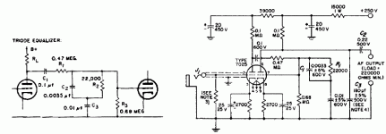
This is what RCA suggested:
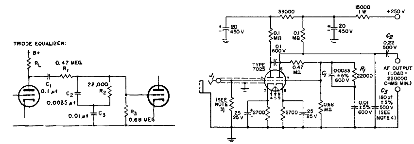
In very round numbers, the RIAA network has loss like:
50Hz---1KHz---20KHz
1/2----1/20---1/200
At 1KHz, if each triode has gain of 45, we have 45*(1/20)*45 which is 100.
However as we may see later, the input levels will be higher. Multiplied by gain of 45 in the first stage, we need to check for overload. OTOH, inputs at the top of the audio band are amplified by 45 then cut-down by 1/200: the level after the EQ is much less than pickup level, and risks getting down into universal hiss. It is a Good Rule to never let small signals (at the edge of hiss) get even smaller. In this plan, the hiss in the final output is dominated, above 5KHz, by the 2nd stage hiss, not the 1st stage. Also the apparent rise of level of 1st stage above the 2nd stage looks dubious, though is probably fine.
Lot of math to compute this. Computers will do math. You have to watch them close, and check against a matchbook, to be sure they are answering the question you want answered.

We know by experience that these 6SC7/12AX7 passive EQ stages are often very satisfactory, due in part to the high overload voltage of tubes.
We do have that apparent 20V at 20KHz on the second stage, with a "flat" (test) input signal. Can that really happen in a phono system?
Let's start by assuming a "flat" test signal was put to the cutter, read out by magnetic pickup, and goes through our phono stage.
Using the nominal 5mV@1KHz pickup sensitivity, and the RIAA curve, our signals will be:
50Hz---1KHz---20KHz
0.5------5------50mV
Impose the RIAA curve around 1KHz:
50Hz---1KHz---20KHz
10-------1-----0.1
Phono gain is often 40dB, gain of 100 at 1KHz. We now have gain of:
50Hz---1KHz---20KHz
1000----100-----10
Multiply through:
50Hz---1KHz---20KHz
0.5------5------50mV--input
1000----100-----10-----gain
***************************
500-----500----500----output
A flat cutter signal makes a flat output signal, as desired.
We "should" go back and plot many in-between frequencies. However the RIAA is smooth and life is short.
The above math works for "single stage" systems such as RIAA in the NFB loop, by now the most common.
However historically RIAA has been done with passive networks between amplifier stages.
Two bad examples: we need gain of 100@1KHz, so 1,000@50Hz. Start with gain=1000, then RIAA-down. This leads to levels like 50V out of the gain stage, which is a lot even for tubes. Conversely, start with lossy RIAA and knock signal down, then gain-up. The loud parts will arrive at the gain stage down in the hiss. Neither is practical.
This is what RCA suggested:
In very round numbers, the RIAA network has loss like:
50Hz---1KHz---20KHz
1/2----1/20---1/200
At 1KHz, if each triode has gain of 45, we have 45*(1/20)*45 which is 100.
However as we may see later, the input levels will be higher. Multiplied by gain of 45 in the first stage, we need to check for overload. OTOH, inputs at the top of the audio band are amplified by 45 then cut-down by 1/200: the level after the EQ is much less than pickup level, and risks getting down into universal hiss. It is a Good Rule to never let small signals (at the edge of hiss) get even smaller. In this plan, the hiss in the final output is dominated, above 5KHz, by the 2nd stage hiss, not the 1st stage. Also the apparent rise of level of 1st stage above the 2nd stage looks dubious, though is probably fine.
Lot of math to compute this. Computers will do math. You have to watch them close, and check against a matchbook, to be sure they are answering the question you want answered.
We know by experience that these 6SC7/12AX7 passive EQ stages are often very satisfactory, due in part to the high overload voltage of tubes.
We do have that apparent 20V at 20KHz on the second stage, with a "flat" (test) input signal. Can that really happen in a phono system?
Attachments
Do we really have big treble in a phono system?
If you have ever spent time with a spectrum display, you know all speech/music slants down on top (high frequencies). This goes with it being hard to make large sources vibrate quickly. It also goes with our ears being tuned to hear high frequencies extra well (the snap of a twig under a tiger's toe, the rustle of a dinner-mouse).
It is also an assumption in the preemphasis applied in FM broadcasting. Hogh frequencies sounds are never loud, we can boost them without distortion, un-boost at the other end, and reduce radio static and other noises. The amount of preemphasis is a matter of debate, and different in US and EUR, different in FM and TV. But a boost starting around 2KHz has been used for over 60 years without much dissatisfaction.
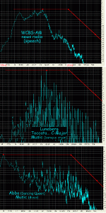
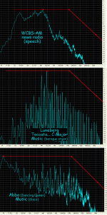
Here's plots I made of speech, organ, and disco, masked under a 2KHz slope.

Only the disco even comes close. Some disco and other tizz-heavy music may have more, but unlikely to be much more-- our ears would bleed.
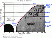
We also have the Shure data of observed record velocities. Lots of dots and blobs. But a simple straight-line approximation is possible, as shown.
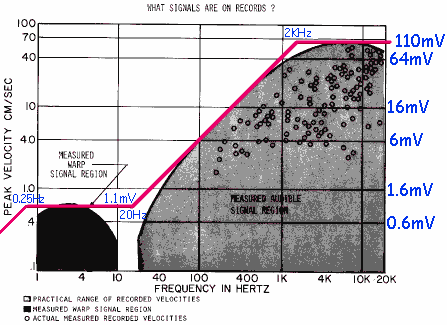
Shure also observed sub-sonic signals (noise, rumble, warp) which does not fit the audio zone trend. Another straight line covers this area. Shure's plot stops at 1Hz, and we know some of our records have 0.55Hz from disc-warp. However this should be a declining area because it is below tonearm resonance so the whole cartridge tends to follow the warp. I have seen trouble from subsonic "bumps" in preamp response, so I like to check this area. I have approximated the subsonic with two more lines jointed at 20Hz and 0.25Hz.
The 10Hz-20Hz gap is odd. They may have needed two different analyzers and they did not overlap. Or it is possible that quality turntables work to minimize 10Hz-20Hz disturbances because they are a "special thing" to our senses, "jiggle". This is the "vibrato" range. It is also the bounce rate of a floor which is not quite solid underfoot. I decided we might have crap 10-20Hz, and if not, fine.
Here is a SPICE source for maximum likely phono signals.

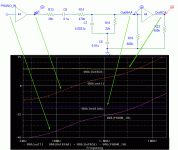
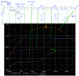
Running these curves against the RCA 2-triode passive-EQ preamp, we see we will not have overload trouble above 5KHz, as we predicted from unrealistic "flat" tests.
This chat started around the Hagerman Bugle2, a passive-EQ preamp, and some general remarks about passive-EQ from Doug Self, which were interpreted to criticize the Bugle2. While my tastes trend to the Self side, Hagerman is an excellent designer. And when you really know your stuff, as both these people do, you learn that you can do things several different ways and, with care, arrive at equally good results. (Or: the electrons don't actually know active from passive EQ.)
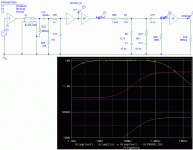
Here's my analysis of the Bugle2's overload anatomy.

No stage approaches the ~~5V overload point except the last stage. 5V really should be enough output for a phono preamp. While our final goals may be higher (perhaps speaker level), that is what Line Amps and Power Amps are for.
No stage has lower input than the stage(s) before it, and not even close until signal is over 0.5V where added hiss becomes insignificant.
The Bugle2 has no subsonic bump, and the level on Shure's subsonics is below overload, we do not expect low frequency crap to disturb it.
Yes, the shapes above 2KHz seem oddly "flat". The observed spectrum roll-off for strong sources is super-similar to the >2KHz boost of the RIAA (and FM) EQ. This merely shows the Old Guys knew their stuff, knew their sounds.
If you have ever spent time with a spectrum display, you know all speech/music slants down on top (high frequencies). This goes with it being hard to make large sources vibrate quickly. It also goes with our ears being tuned to hear high frequencies extra well (the snap of a twig under a tiger's toe, the rustle of a dinner-mouse).
It is also an assumption in the preemphasis applied in FM broadcasting. Hogh frequencies sounds are never loud, we can boost them without distortion, un-boost at the other end, and reduce radio static and other noises. The amount of preemphasis is a matter of debate, and different in US and EUR, different in FM and TV. But a boost starting around 2KHz has been used for over 60 years without much dissatisfaction.
Here's plots I made of speech, organ, and disco, masked under a 2KHz slope.
Only the disco even comes close. Some disco and other tizz-heavy music may have more, but unlikely to be much more-- our ears would bleed.
We also have the Shure data of observed record velocities. Lots of dots and blobs. But a simple straight-line approximation is possible, as shown.
Shure also observed sub-sonic signals (noise, rumble, warp) which does not fit the audio zone trend. Another straight line covers this area. Shure's plot stops at 1Hz, and we know some of our records have 0.55Hz from disc-warp. However this should be a declining area because it is below tonearm resonance so the whole cartridge tends to follow the warp. I have seen trouble from subsonic "bumps" in preamp response, so I like to check this area. I have approximated the subsonic with two more lines jointed at 20Hz and 0.25Hz.
The 10Hz-20Hz gap is odd. They may have needed two different analyzers and they did not overlap. Or it is possible that quality turntables work to minimize 10Hz-20Hz disturbances because they are a "special thing" to our senses, "jiggle". This is the "vibrato" range. It is also the bounce rate of a floor which is not quite solid underfoot. I decided we might have crap 10-20Hz, and if not, fine.
Here is a SPICE source for maximum likely phono signals.
Running these curves against the RCA 2-triode passive-EQ preamp, we see we will not have overload trouble above 5KHz, as we predicted from unrealistic "flat" tests.
This chat started around the Hagerman Bugle2, a passive-EQ preamp, and some general remarks about passive-EQ from Doug Self, which were interpreted to criticize the Bugle2. While my tastes trend to the Self side, Hagerman is an excellent designer. And when you really know your stuff, as both these people do, you learn that you can do things several different ways and, with care, arrive at equally good results. (Or: the electrons don't actually know active from passive EQ.)
Here's my analysis of the Bugle2's overload anatomy.
No stage approaches the ~~5V overload point except the last stage. 5V really should be enough output for a phono preamp. While our final goals may be higher (perhaps speaker level), that is what Line Amps and Power Amps are for.
No stage has lower input than the stage(s) before it, and not even close until signal is over 0.5V where added hiss becomes insignificant.
The Bugle2 has no subsonic bump, and the level on Shure's subsonics is below overload, we do not expect low frequency crap to disturb it.
Yes, the shapes above 2KHz seem oddly "flat". The observed spectrum roll-off for strong sources is super-similar to the >2KHz boost of the RIAA (and FM) EQ. This merely shows the Old Guys knew their stuff, knew their sounds.
Attachments
> ...keep going!
Let me first put in a free but sincere plug for Douglas Self's works:
Small Signal Audio Design
Electronics for Vinyl
"Small.." is basics for all audio. "..Vinyl" focuses on phono stages, covers some of what I'm saying here, and much-MUCH more. If you are even *thinking* about phono design, even just to study existing designs, you want to read these. Both. Twice.
me> Shure data ....maximum likely phono signals.
I've showed possible HF trouble in RCA's 2-triode passive-EQ plan. To clarify this, I showed that treble levels fall-off. This particularly benefits global-NFB EQ schemes, which strain against the RIAA capacitors going near short at the top of the audio band (they can still suffer). I also plotted Shure's data including the lump down to 1Hz.
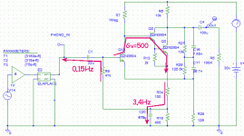
Here is a VERY common topology, used by almost everybody around 1970.

I knew several such phono preamps, which measured fine and flat and gave good headroom over the audio band, but sometimes had "unsteadiness" on some warped discs and/or some turntables or tonearms. Sometimes they outright flapped "for no reason".
In days when signal generators went down to 20Hz, the subsonic response was whatever it was. I had a Heath which went to sub-Hz and modified a VTVM to be flat (though very slow) down there.
I (and others) identified a subsonic bump in this plan. R34 and C20 form a pole. R9 and C1 form another pole. This is wrapped around a high-gain stage (to set DC bias). Even when the two poles are staggered 20:1, as shown, you can have a 10dB bump below the audio band. (I have seen worse.)

Does this matter? Nobody cuts vinyl below 20Hz (probably not <50Hz). However our discs are never quite flat, our turntables are mere machines, and tonearms have mass and stiffness so must have a resonance. Shure identified cartridge output far below the "audio" band. Let's run their numbers against this design. Set the nominal cartridge audio output to touch the benchmark 5V overload level. Feed the 0.1Hz-up levels from the Shure data.

Yowsa! The sub-sonics can be 3X bigger than the loud parts of the music!
And music rises and falls. Rumble and warp can be more constant.
OTOH the Shure data is probably worst-case. No turntable is likely to fill that whole 1Hz-10Hz range all the time. If a specific rig is mostly a 1.4Hz thud it falls well away from the bump and may not matter.
If it thuds near 2.6Hz we have huge subsonic signals. In an extreme case the preamp output "flaps" as it clips. If it "only" pushes the preamp into a non-linear range (say over 2V) then it will intermodulate the audio and throw sidebands +/-2.6Hz of every tone in the output; for complex tones (music) this is a "haze". It also messes with our pitch perception. And because 2.6Hz is within the "jiggle/flutter" range of human perception, it is unsettling like a cheaply framed floor.
Personal Note: I've wrassled with this plan, on and off, for decades. I even looked at SuperCaps when they appeared around 1980, but the ESR was high. Recently I noted that ESR is down and so is price (50 FARADs for a few bucks??). Running this in SPICE I realized that stability in the LF range must be mirror-image to what we aim for in the HF range of NFB amplifiers: a single-pole slope over the gain inside the loop. When SPICE starts it, it sims nicely. However if I cold-start it, make all caps charge from zero, the start-up time is DAYS. This would make it awkward on the breadboard and an energy hog in the listening room (to leave it on 24/7). Yes, it could be hacked with relays to pre-charge, but loses the essential elegance of a few-transistor preamp.
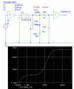
OTOH, the Bugle2 does not have any problem with Shure's sub-sonics. Of course it has no sub-sonic resonance because it pulls no tricks to get DC bias. Subsonics are not raised in stages 1 or 2, and it has a sub-sonic cut-off before the last amplifier stage.
My Pioneer A-757 has a different but similar plan. The first stage is opamp with RIAA NFB, but without the 75uS kink, and gain near 16 (not 50). The 75uS pole is then taken passively. Then a second stage gives gain of 3.3, and an optional 20Hz 2-pole subsonic filter. With no subsonic bump and gain after the subsonic filter it can't be stressed by our expected subsonics.
I've showed possible HF trouble in RCA's 2-triode passive-EQ plan. To clarify this, I showed that treble levels fall-off. This particularly benefits global-NFB EQ schemes, which strain against the RIAA capacitors going near short at the top of the audio band (they can still suffer). I also plotted Shure's data including the lump down to 1Hz.
Here is a VERY common topology, used by almost everybody around 1970.
I knew several such phono preamps, which measured fine and flat and gave good headroom over the audio band, but sometimes had "unsteadiness" on some warped discs and/or some turntables or tonearms. Sometimes they outright flapped "for no reason".
In days when signal generators went down to 20Hz, the subsonic response was whatever it was. I had a Heath which went to sub-Hz and modified a VTVM to be flat (though very slow) down there.
I (and others) identified a subsonic bump in this plan. R34 and C20 form a pole. R9 and C1 form another pole. This is wrapped around a high-gain stage (to set DC bias). Even when the two poles are staggered 20:1, as shown, you can have a 10dB bump below the audio band. (I have seen worse.)
Does this matter? Nobody cuts vinyl below 20Hz (probably not <50Hz). However our discs are never quite flat, our turntables are mere machines, and tonearms have mass and stiffness so must have a resonance. Shure identified cartridge output far below the "audio" band. Let's run their numbers against this design. Set the nominal cartridge audio output to touch the benchmark 5V overload level. Feed the 0.1Hz-up levels from the Shure data.
Yowsa! The sub-sonics can be 3X bigger than the loud parts of the music!
And music rises and falls. Rumble and warp can be more constant.
OTOH the Shure data is probably worst-case. No turntable is likely to fill that whole 1Hz-10Hz range all the time. If a specific rig is mostly a 1.4Hz thud it falls well away from the bump and may not matter.
If it thuds near 2.6Hz we have huge subsonic signals. In an extreme case the preamp output "flaps" as it clips. If it "only" pushes the preamp into a non-linear range (say over 2V) then it will intermodulate the audio and throw sidebands +/-2.6Hz of every tone in the output; for complex tones (music) this is a "haze". It also messes with our pitch perception. And because 2.6Hz is within the "jiggle/flutter" range of human perception, it is unsettling like a cheaply framed floor.
Personal Note: I've wrassled with this plan, on and off, for decades. I even looked at SuperCaps when they appeared around 1980, but the ESR was high. Recently I noted that ESR is down and so is price (50 FARADs for a few bucks??). Running this in SPICE I realized that stability in the LF range must be mirror-image to what we aim for in the HF range of NFB amplifiers: a single-pole slope over the gain inside the loop. When SPICE starts it, it sims nicely. However if I cold-start it, make all caps charge from zero, the start-up time is DAYS. This would make it awkward on the breadboard and an energy hog in the listening room (to leave it on 24/7). Yes, it could be hacked with relays to pre-charge, but loses the essential elegance of a few-transistor preamp.
OTOH, the Bugle2 does not have any problem with Shure's sub-sonics. Of course it has no sub-sonic resonance because it pulls no tricks to get DC bias. Subsonics are not raised in stages 1 or 2, and it has a sub-sonic cut-off before the last amplifier stage.
My Pioneer A-757 has a different but similar plan. The first stage is opamp with RIAA NFB, but without the 75uS kink, and gain near 16 (not 50). The 75uS pole is then taken passively. Then a second stage gives gain of 3.3, and an optional 20Hz 2-pole subsonic filter. With no subsonic bump and gain after the subsonic filter it can't be stressed by our expected subsonics.
Attachments
Great series of posts, PRR. 
But in the case of my 'classic tube design' "Muse" phono stage - 2x JFET gain stages with a passive RIAA network in between - I have not experienced any headroom problems, using a 24v (SE) DC rail?
I make it in some different gain configurations but, for example:
* MM:
** input 5mV
** 1st gain stage output - 300mV (x60)
** RIAA output - 30mV
** 2nd gain stage output - 1,200mV (x40).
* MC:
** input 0.3mV
** 1st gain stage output - 150mV (x500)
** RIAA output - 15mV
** 2nd gain stage output - 1,200mV (x80).
Andy
....in the case of my 'classic tube design' "Muse" phono stage
Good to give a LINK so we all on a same page.
I have not experienced any headroom problems, using a 24v (SE) DC rail?
It is certainly well-optimized.
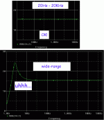
Rather than sim the JFET stages I just assumed they were near-ideal amps with gains of 60 and 30, ample bandwidth, and near rail-to-rail output.
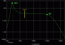
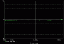
The frequency response is frighteningly flat - I had to check I was really reading the output. The 0.1dB curve may not be real because of my simplified model. The rise at 20KHz is due to the zero at 50KHz (194r) which is a matter of debate but a non-issue.
The gain using these values works out to 45dB.
Using "my" torture test, using the highest recorded levels through the higher output MM cartridges, the sim says 10.2V worst-case and by inspection the JFETs can swing 8V. "Fail"? No, because if you did have one of the higher-output needles you would find that 45dB is more gain than you want/need, and trim it down to maybe 39dB. Now you have at-most 5V signal, so your 8V clip-point is ample. (Note again that I am not simulating FET linearity and do not know the THD.)
Attachments
Another reference, not digested, is the Holman paper:
Holman, Dynamic Range Phono Preamplifiers, Audio July 1977. - Pro Audio Design Forum
Extensive study of subsonics.
Holman, Dynamic Range Phono Preamplifiers, Audio July 1977. - Pro Audio Design Forum
Extensive study of subsonics.
My measured figure on a G1022 hitting a record defect, was 200mV peak to peak, ringing at 19kHz. This is way above the Shure music curve.What are the signal characteristics produced by dust and scratches and how do they fit the headroom model ?....we have all heard phono preamps that produce a benign quiet 'tick' on dust, and others that 'crack' loudly on dust/scratches.
Dan.
5V rms is too high for a lot of amplifiers with solid state input switching......No stage approaches the ~~5V overload point except the last stage. 5V really should be enough output for a phono preamp. While our final goals may be higher (perhaps speaker level), that is what Line Amps and Power Amps are for.....
I wonder if a deliberate soft limiting at high levels, maybe even more severe limiting at cantilever resonance frequency, might give good results
- Status
- This old topic is closed. If you want to reopen this topic, contact a moderator using the "Report Post" button.
- Home
- Source & Line
- Analogue Source
- Gain, Overload, Headroom -- not as hard as Gödel, Escher, Bach
