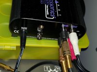
I just finished a few modifications on my Art Djpre II, and thought I'd share them with the DIY community.
The first thing I changed was the power supply.
Many owners of this unit report that it sounds much better on battery power, or as reported in this post it can sound just as nice with a good quality regulated supply.
Cheap upgrade for Art DJ Pre ii owners : vinyl
I looked at the one they suggested from Parts Express, but given that it is made by Mean Well, who to my knowledge only makes switching type supplies (which would introduce a lot of switching noise) I chose instead to build my own ripple filtered & regulated supply.
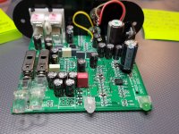
The original wall wart was 9VAC, which is rectified inside the chassis with small SMD diodes in a full wave bridge configuration.
The first filter cap is a 470uf, immediately after which the voltage is regulated down to 5VDC.
Since battery power improves the sound so much, my assumption is that everything after the regulator is of sufficient quality that little improvement could be made from there on.
So, I saw the 470uf cap as a good place to start.
The original is made by Junfu.
They are generally considered low grade crap, so I began the hunt for something better, and decided after reading probably way too much about the subject that an Elna Silmic II would be a substantial upgrade.
The first change was to replace the first filter cap C5 with an Elna Silmic II 470uf @ 25V.
The Elna is slightly larger than the original, but did fit with a slight bend in the leads.
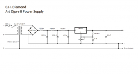
The power supply I came up with is pretty straight forward, and has a nice clean output.
It should be adjusted to 12VDC.
I was a bit skeptical of the difference these changes would make, but listening tests confirmed what others have noticed.
Quieter, more dynamic, improved depth & clarity.
I could have quit at that point, but then I had another small thing to work out.
I am using the Djpre II with an Ortofon 2M Blue.
The inductance of this cartridge is rated at 700mh, which I confirmed measures 728mh with an inductance meter.
With the capacitance of the tonearm cable, interconnects, and the Djpre II internal loading capacitance of 100pf, I was getting a resonant peak at roughly 11.4khz give or take, which was readily apparent in listening tests.
This page has a calculator to estimate resonant peaking with various capacitance loads, and explains really well the effects of changing the cartridge load.
Hagerman Technology LLC: Cartridge Loading
So, it seemed pretty clear that I needed to shed every pf I could to get closer to ideal frequency response from this cartridge.
I tried low capacitance cables, which helped a bit, but it still wasn't low enough capacitance to get rid of that resonant peak within my hearing range.
I briefly considered going with a lower inductance cartridge like a Grado, but where's the fun in that?
I contacted ART and asked for a schematic, but they said that they no longer provide schematics for their current line of products, because they have had some of their designs stolen by other companies.
Since I was only looking to tune the input capacitance, I really didn't need the entire schematic, so I contacted them again and described my problem, and what I was trying to do.
The ART QC engineer consulted the Design engineer who both shared their knowledge of this circuit and helped me to get rid of that last 100pf load capacitance, which in turn got rid of the resonant peak (at least to my ears).
I would like to thank both of them for their help.
It was much appreciated.
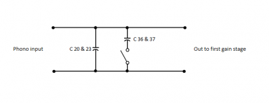
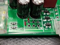
So, here it is.
C20 & C23 are the 100pf cartridge load capacitors.
They stay across the input all the time.
C36 & C37 are both 100pf capacitors which are switched in parallel with the fixed capacitors (C20 & C23) to achieve 200pf loading.
Removing C20 & C23 gives you 0pf load on the 100pf setting, and 100pf load on the 200pf setting.
It's as simple as that.
Without giving away any of their trade secrets, I made the overly simplified schematic of the input loading circuit as a way to visualize the effect of removing C20 & C23.
The first thing I changed was the power supply.
Many owners of this unit report that it sounds much better on battery power, or as reported in this post it can sound just as nice with a good quality regulated supply.
Cheap upgrade for Art DJ Pre ii owners : vinyl
I looked at the one they suggested from Parts Express, but given that it is made by Mean Well, who to my knowledge only makes switching type supplies (which would introduce a lot of switching noise) I chose instead to build my own ripple filtered & regulated supply.
The original wall wart was 9VAC, which is rectified inside the chassis with small SMD diodes in a full wave bridge configuration.
The first filter cap is a 470uf, immediately after which the voltage is regulated down to 5VDC.
Since battery power improves the sound so much, my assumption is that everything after the regulator is of sufficient quality that little improvement could be made from there on.
So, I saw the 470uf cap as a good place to start.
The original is made by Junfu.
They are generally considered low grade crap, so I began the hunt for something better, and decided after reading probably way too much about the subject that an Elna Silmic II would be a substantial upgrade.
The first change was to replace the first filter cap C5 with an Elna Silmic II 470uf @ 25V.
The Elna is slightly larger than the original, but did fit with a slight bend in the leads.
The power supply I came up with is pretty straight forward, and has a nice clean output.
It should be adjusted to 12VDC.
I was a bit skeptical of the difference these changes would make, but listening tests confirmed what others have noticed.
Quieter, more dynamic, improved depth & clarity.
I could have quit at that point, but then I had another small thing to work out.
I am using the Djpre II with an Ortofon 2M Blue.
The inductance of this cartridge is rated at 700mh, which I confirmed measures 728mh with an inductance meter.
With the capacitance of the tonearm cable, interconnects, and the Djpre II internal loading capacitance of 100pf, I was getting a resonant peak at roughly 11.4khz give or take, which was readily apparent in listening tests.
This page has a calculator to estimate resonant peaking with various capacitance loads, and explains really well the effects of changing the cartridge load.
Hagerman Technology LLC: Cartridge Loading
So, it seemed pretty clear that I needed to shed every pf I could to get closer to ideal frequency response from this cartridge.
I tried low capacitance cables, which helped a bit, but it still wasn't low enough capacitance to get rid of that resonant peak within my hearing range.
I briefly considered going with a lower inductance cartridge like a Grado, but where's the fun in that?
I contacted ART and asked for a schematic, but they said that they no longer provide schematics for their current line of products, because they have had some of their designs stolen by other companies.
Since I was only looking to tune the input capacitance, I really didn't need the entire schematic, so I contacted them again and described my problem, and what I was trying to do.
The ART QC engineer consulted the Design engineer who both shared their knowledge of this circuit and helped me to get rid of that last 100pf load capacitance, which in turn got rid of the resonant peak (at least to my ears).
I would like to thank both of them for their help.
It was much appreciated.
So, here it is.
C20 & C23 are the 100pf cartridge load capacitors.
They stay across the input all the time.
C36 & C37 are both 100pf capacitors which are switched in parallel with the fixed capacitors (C20 & C23) to achieve 200pf loading.
Removing C20 & C23 gives you 0pf load on the 100pf setting, and 100pf load on the 200pf setting.
It's as simple as that.
Without giving away any of their trade secrets, I made the overly simplified schematic of the input loading circuit as a way to visualize the effect of removing C20 & C23.
Attachments
APPLIED RESEARCH AND TECHNONOGY Model "ARTDJ PRE-II" - Schematic wanted
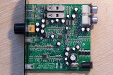
I want to have the circuit diagram of this cheap and interesting RIAA Pre-Amplifier, which work with 3 pcs 9721 (LME49721) in a SO-8 outline.
Then I will find out, which steps are effortless resp. easy and enhance the sound at the same time.
Maybe one of the member can upload this. - thank you very much
here some links and images from inside
DJPRE II – Phono Preamplifier – ART Pro Audio
support@artproaudio.com
The ART Pro Audio DJ PRE II preamp. The best preamp bargain out there? | Page 2 | Steve Hoffman Music Forums
Art DJ Pre II Gain Level?? | Audiokarma Home Audio Stereo Discussion Forums
ART DJ Pre II op amps ? | Audiokarma Home Audio Stereo Discussion Forums
Cheap upgrade for Art DJ Pre ii owners : vinyl
https://www.thomann.de/de/art_deejaypre_ii.htm?ref=search_prv_9
https://www.analog-forum.de/wbboard...j-pre-2-ein-test-mit-dem-denon-dl-103-teil-i/
http://www.hifi-forum.de/viewthread-26-23192.html#7
Attachments
Thanks for this - but if you're feeding the preamp PS w/ a DC supply the filter capacitors shouldn't really matter (unless your DC supply is not very good).
I have a new scope coming next week and the Parts Express supply, so I am going to look and see how much ripple is coming out of the Parts Express supply and what is happening after the various stages in the Art supply (rectifier, filter caps, regulator).
I have a new scope coming next week and the Parts Express supply, so I am going to look and see how much ripple is coming out of the Parts Express supply and what is happening after the various stages in the Art supply (rectifier, filter caps, regulator).
Last edited by a moderator:
to chd_diy if you happen to be reading, I followed your mod of removing C20 & C23 to drop the load capacitance to 0pF (& 100pF respectively), but noticed that the unit picked up a bit of background hum as a result (maybe related, maybe not). I am wondering if you noticed any hum after the mod? Did you short across the pads or just removed the caps?
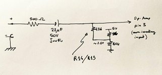
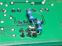
I found out myself: they are R14 and R15. I replaced them with a potentiometer in order to adjust the input impedence, since I am using an AT-440mlb cartridge and it was too much bright.
In the picture attached you can find the input schematic too. A possible upgrade could be to add a film cap to help the electrolytic one.
In the picture attached you can find the input schematic too. A possible upgrade could be to add a film cap to help the electrolytic one.
Attachments
Sincerely I don't know. I absolutely agree with you... I would have to open it again, but since now it's full of patch wires (I just added polystyrene caps in parallel to 22uF) it would be a pain....The lower 10k in the resistor divider probably has a capacitor of at least 10 µF in parallel, doesn't it? (Wouldn't be good if it didn't.)
As for the added caps, yesterday I had a quick listening: it seemed to make a real difference, but I will update this.

Update: two polystyrene caps seem to render a more natural and balanced sound, in particular in the midrange (let's say between 300Hz and 6kHz). If anyone want to try, I can upload some photos to help connections.
I am interested to know what you changed with photos. Thanks.
I am interested to know what you changed with photos. Thanks.
My mod list is the following:
- Replaced blue LED woth red one
- Added power supply switch (to do this, I interrupted -cut- traces on the bottom of the PCB).
- added 100uF alu-polymer cap just after 5V regulator
added 1000uF alu-polymer cap on opamp pins (I assume they have the same rails so doesn't matter which one)
- removed R14 and R15 and installed a 47k stereo potentiometer as load resistance (I use the pot as a series resistor - check if resistance is matched between two channels and in case, correct it with parallel resistor)
- added film polystyrene coupling capacitors [470nF] in parallel to the already present 22uF crappy electrolytics.
- added 1nF caps to rectifing diodes (even if I would like to test a DC supply, since I guess that those wires (and traces) going/coming to/from the switch, even if twisted, spread some noise
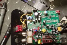
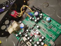
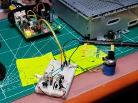
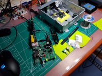
As you can see in pictures, now the case is pretty crowded and moreover wires soldered to 0603 SMD pads are delicate, so I wouldn't want to open it again, since last time I had to open and close 3 times before everything was safe and connected in place (every time 1 wire broken its solder).
I understand my explanations are a bit brief here...if you don't understand something, just ask. Anyway a multimeter with short circuit test and ohmeter helps much to understand connections.
Attachments
Last edited:
AT-440mlb. If you read reviews, a lot of people says it's too bright, I agree, but it depends on many factors: cables, input network and so on. My hypothesis is if you lower load resistance (let's say around 25-30k) the Q factor of the resonating network created by load capacitor/ cable capacitance (my cable capacitance is 200pF measured) and cartridge inductance decreases so sound becomes less bright, more balanced. And I can prove is effective
I forgot to add in modification list that I also removed 100pF load caps.
I forgot to add in modification list that I also removed 100pF load caps.
Last edited:
The old AT75E seems to be much the same. I've got one on a 'table that has something like 3 m worth of cable due to previous mods. Add a standard 47k||220p input, and the treble peak wants to eat your ears for breakfast (though it sounds clean otherwise, so I doubt it's the stylus - I bought a spare just in case). Originally the cable would have been much shorter, and the phono input in the amplifier that went with the unit had 47 pF of input C, bringing the total close to the upper end of the recommended 100-200 pF load range.
Decreasing the R is an old trick that helps taming such critical cartridges, at the expense of response dropping off earlier at the top end. All very easy to simulate, too.
From a noise perspective, it would actually be desirable to further increase the R. That would definitely require a plinth-mounted pre and possibly some trickery like bootstrapping the arm/shield connection. Has anyone tried mounting a buffer near the actual cartridge yet? We've got super tiny / light electronic components these days.
Last edited:
Hi, all
thank you all for giving me insight into the potential and possibilities for improving an already very solid pre-amplifier design.
Even as audio design is not my primary sphere of interest, the recent transition to LP records and my effort to do the de-claudization and return to analogue "value" starting form the beginning of this year, made me interested in the improvement of the existing gramophone pre-amplifier. the fact that I got a built-in preamp with the Pioneer PLX500 gave me the freedom to upgrade the ART DJ-PRE II that I get as a reserve.
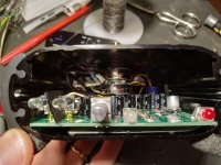
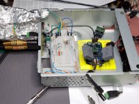
After a thorough analysis of the original set, I noticed that it has a terribly prominent harmonic at 50Hz and its orders. I became interested in the improvement, so I attached it to my linear laboratory power supply and noticed that the harmonic can be suppressed, but also that the device can work with 6.5 - 7V DC, and that it gets heated on one side when connected to an AC power supply.
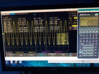
The test with the function generator showed a terrible tendency towards the appearance of harmonics of any dominant frequency (100,500,1kHz ...).
Keeping all the above in mind and knowing the tendency of fellow Audio "gurus" to create things "by ear" because in this engineering field 2+2 can be 6,613 etc. I decided to open the "thing" and see what it was doing. The first thing that caught my eye was the disproportionately poor design of the AC-DC conversion block, the Graetz bridge, then a small 470uF, then the Linear Regulator 7805 at 5V, and after that a small output filter, and only on the Op.Amp is it individually filtered, whatever arrives to them. An ordinary 7805 introduces no less than 50uV of voltage (AC phase) noise, which a good audio Op.Amp with SVR/PSR of -110/120dB easily rejects, but that is not the case here.
Why is it, because someone concluded that a simple CMOS op-amp with low en. of 4nV/Hz (at 100kHz!) is enough to get a solution that will be Low-Noise, "well, litle tomorrow, maybe never". The ST TS972 has a typical SVR of -70dB which means it attenuates the noise level in the power supply by about 3162 times, before it appears as a parasitic value at the input of the Op.Amp. We all know that after that it will be 100 to 178 times more amplified. And the result of all that is the hum that can be heard and clearly seen on spectrographs.
The next characteristic of the TS972 is a THD (no noise, distortion only) of 0.003% which means that the first next harmonic will be 3.0E-5 weaker than the carrier signal which is only -90dB, if you think that is a lot add to this value and noise and gain and there you are in the audible range of below -70/80dB. But wait THD value is for AV=-1 only.
Since this Op.Amp needs to amplify the signal from the turntable whose resistance in the case of the MM head is below 1k Ohm, FET and CMOS solutions with low In in the fA/√Hz range are no advantage, moreover the high resistance at their input increases the thermal noise (Johnson-Nyquist noise).
So for a good solution we need any bipolar Op.Amp that can give at least SVR of -110/120dB, and below 8nV/√Hz at 10, 100Hz and even at 1kHz (and not in the ultrasonic range at 100kHz like TS972).
Also, the distortion should be displayed in the gain mode, not like the built-in ST TS972 where Total harmonic distortion is shown at f = 1 kHz, AV = -1!!!, RL = 10 kΩ is 0.003 % This THD is shown in ideal conditions for CMOS (like any other Op.Amp) since there is no Av=-1 gain and the output load is huge, nowhere near practical application for headphones or studio equipment set of 32,45...90 or 600Ohm (or even for 1k and 2.2 kOhm according to RIAA spec.) This practically means that it is clear why the distorted images are such an expression because 0.003% at 1k becomes 0.03% and when it is amplified 20 times Av=20 ie. 26dB increases to 0.6%, i.e. -44.4dB difference between the carrier tone and its first harmonic.
So I took it upon myself to search the net to see if I was the only one who noticed these anomalies because the searches are full of praise and wonderful reviews full of praise for the -80dB characteristics of this pre-amplifier with also "little" distortion. So the device is even included in reviews and in the analyzes where it is compared with 100-200 USD more expensive models that show similar (in my opinion, frankly poor) characteristics.
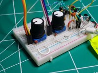
All in all, since this post was long enough to make it a little shorter, I tore out all the Op.Amps, Ordinary electrolytic capacitors and thoroughly reworked the power supply with the necessary addition of components.
Since my idea was not to turn a 50 USD device into a 500 USD beast, I gave up on the OPA1612 or OPA2228 which were my primary choice, since the existing state of my inventory with 3-4 pieces I can't possibly replace due to the lack of components on the market and price hikes, I deside to save them for some other/new projects. Next I tested the LM4562 and its successor family LME497xxx and since I couldn't find a reasonably priced SOIC versionI abandoned them also, I decided on the suggestion made by NwAvGuy in his analysis. Honestly my favorite for a cheap solution was the NE5532A at first, but it The NJM4580D outperformed it in my tests, and only one small thing decided that I should include the NJM2068D (MD) in the design instead, and that is the equivalent noise level, which in my tests is just behind the leading trio of OPA1612/1602, OPA 2228, and LM4562... even more form 1-10Hz up to about 400Hz its noise level is lower than LM4562 or OP227. LT1028 hash lowest values but i is best that is it hard to teme.
And it has specified and garanted RIAA caracteristics NJM2068D Equivalent Input Noise Voltage is as FLAT+JIS A, on RS=300Ω at 0.44 to max 0.56μVp-p
Spec do not show its en(Equivalent Input Noise) value but it si perform better then 3-4nV/√Hz devices on 10, 100 and 1kHz so it have to be below 4nV/√Hz.
Even its mediocre THD-N is shown at near real situation as sum of THD with Noise at AV=20dB gain amplification, VO=5V, RL=2kΩ, f=1kHz and it is THD-N is 0,001%
Simular new design NJM8068 (repackaging) spefied also as 0.001% even show that it can go as low to 0,0007% at AV=100 at 8-9V output.
When Ti put in spec for OPA1612 as stellar level for THD-N like 0.000015%, we must have in mind that it is mesured on no gain platform AV=+1 so that real condition Pre.Amp wil degrade that for any aplification level it performs, so at AV=100 (20dB relative) it is =
20x Log(THD-N/100)+ 20x Log(AV) ---> -136.478+40 => -96.478dB which is translated to NJM specs equal to 100% * 10^(-96.478dB/20) = 0.0015%
Now it is clear why on practical tests "King of the hill" is not always one that we all expect to be.
And the most important thing is when all supplier have stuff an waiting until next year, I managed to buy them for 1 USD each.
My mod list is the following:
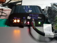
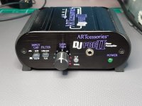
Replaced blue LED with green LED which is much dimer
Added On/Off switch on chassis
Added power supply switch (to do this, I interrupted -cut- traces on the bottom of the PCB).
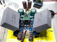
Added 2200uF/25V LowESR high ripple electrolytic Cap. (brand name)
Boost working condition by replacing 5V (Korean) for ST L7810A low noise 10V linear regulator
Added Lin. Reg protection diode for hi cap. load switching
Added another 2200u/25V LowESR high ripple electrolytic Cap. (brand name)
Replace all onboard ordinary electrolytic Cap. and replace them with audio grade (brand name) equivalent LowESR high ripple electrolytic Cap From Panasonic and Samwa.
Replace 1uF electrolytic on WIMA MKP in audio path and with MKT on power path.
Replace condensers for 100pF input filtering
Replace addition 100pF condensers for 200pF filtering with 220pF NP0 ones, so that now I have 0pF and 220pF input filtering
And most importantly I replace TS972 with little larger NJM2068MD (D-sufix version for guaranteed RIAA req.)
This post is becoming even longer so I will put all other stuff to my blog
 vs Original DJ-Pre II (Blue) -- Nosie level comparation 50Om terminated inpout ...png")


All of this I will explain and post soon to my blog on Hackadey, so fill free to visit it:
https://hackaday.io/JovanE
Best regards ,
Dr Jovan I.
thank you all for giving me insight into the potential and possibilities for improving an already very solid pre-amplifier design.
Even as audio design is not my primary sphere of interest, the recent transition to LP records and my effort to do the de-claudization and return to analogue "value" starting form the beginning of this year, made me interested in the improvement of the existing gramophone pre-amplifier. the fact that I got a built-in preamp with the Pioneer PLX500 gave me the freedom to upgrade the ART DJ-PRE II that I get as a reserve.
After a thorough analysis of the original set, I noticed that it has a terribly prominent harmonic at 50Hz and its orders. I became interested in the improvement, so I attached it to my linear laboratory power supply and noticed that the harmonic can be suppressed, but also that the device can work with 6.5 - 7V DC, and that it gets heated on one side when connected to an AC power supply.
The test with the function generator showed a terrible tendency towards the appearance of harmonics of any dominant frequency (100,500,1kHz ...).
Keeping all the above in mind and knowing the tendency of fellow Audio "gurus" to create things "by ear" because in this engineering field 2+2 can be 6,613 etc. I decided to open the "thing" and see what it was doing. The first thing that caught my eye was the disproportionately poor design of the AC-DC conversion block, the Graetz bridge, then a small 470uF, then the Linear Regulator 7805 at 5V, and after that a small output filter, and only on the Op.Amp is it individually filtered, whatever arrives to them. An ordinary 7805 introduces no less than 50uV of voltage (AC phase) noise, which a good audio Op.Amp with SVR/PSR of -110/120dB easily rejects, but that is not the case here.
Why is it, because someone concluded that a simple CMOS op-amp with low en. of 4nV/Hz (at 100kHz!) is enough to get a solution that will be Low-Noise, "well, litle tomorrow, maybe never". The ST TS972 has a typical SVR of -70dB which means it attenuates the noise level in the power supply by about 3162 times, before it appears as a parasitic value at the input of the Op.Amp. We all know that after that it will be 100 to 178 times more amplified. And the result of all that is the hum that can be heard and clearly seen on spectrographs.
The next characteristic of the TS972 is a THD (no noise, distortion only) of 0.003% which means that the first next harmonic will be 3.0E-5 weaker than the carrier signal which is only -90dB, if you think that is a lot add to this value and noise and gain and there you are in the audible range of below -70/80dB. But wait THD value is for AV=-1 only.
Since this Op.Amp needs to amplify the signal from the turntable whose resistance in the case of the MM head is below 1k Ohm, FET and CMOS solutions with low In in the fA/√Hz range are no advantage, moreover the high resistance at their input increases the thermal noise (Johnson-Nyquist noise).
So for a good solution we need any bipolar Op.Amp that can give at least SVR of -110/120dB, and below 8nV/√Hz at 10, 100Hz and even at 1kHz (and not in the ultrasonic range at 100kHz like TS972).
Also, the distortion should be displayed in the gain mode, not like the built-in ST TS972 where Total harmonic distortion is shown at f = 1 kHz, AV = -1!!!, RL = 10 kΩ is 0.003 % This THD is shown in ideal conditions for CMOS (like any other Op.Amp) since there is no Av=-1 gain and the output load is huge, nowhere near practical application for headphones or studio equipment set of 32,45...90 or 600Ohm (or even for 1k and 2.2 kOhm according to RIAA spec.) This practically means that it is clear why the distorted images are such an expression because 0.003% at 1k becomes 0.03% and when it is amplified 20 times Av=20 ie. 26dB increases to 0.6%, i.e. -44.4dB difference between the carrier tone and its first harmonic.
So I took it upon myself to search the net to see if I was the only one who noticed these anomalies because the searches are full of praise and wonderful reviews full of praise for the -80dB characteristics of this pre-amplifier with also "little" distortion. So the device is even included in reviews and in the analyzes where it is compared with 100-200 USD more expensive models that show similar (in my opinion, frankly poor) characteristics.
All in all, since this post was long enough to make it a little shorter, I tore out all the Op.Amps, Ordinary electrolytic capacitors and thoroughly reworked the power supply with the necessary addition of components.
Since my idea was not to turn a 50 USD device into a 500 USD beast, I gave up on the OPA1612 or OPA2228 which were my primary choice, since the existing state of my inventory with 3-4 pieces I can't possibly replace due to the lack of components on the market and price hikes, I deside to save them for some other/new projects. Next I tested the LM4562 and its successor family LME497xxx and since I couldn't find a reasonably priced SOIC versionI abandoned them also, I decided on the suggestion made by NwAvGuy in his analysis. Honestly my favorite for a cheap solution was the NE5532A at first, but it The NJM4580D outperformed it in my tests, and only one small thing decided that I should include the NJM2068D (MD) in the design instead, and that is the equivalent noise level, which in my tests is just behind the leading trio of OPA1612/1602, OPA 2228, and LM4562... even more form 1-10Hz up to about 400Hz its noise level is lower than LM4562 or OP227. LT1028 hash lowest values but i is best that is it hard to teme.
And it has specified and garanted RIAA caracteristics NJM2068D Equivalent Input Noise Voltage is as FLAT+JIS A, on RS=300Ω at 0.44 to max 0.56μVp-p
Spec do not show its en(Equivalent Input Noise) value but it si perform better then 3-4nV/√Hz devices on 10, 100 and 1kHz so it have to be below 4nV/√Hz.
Even its mediocre THD-N is shown at near real situation as sum of THD with Noise at AV=20dB gain amplification, VO=5V, RL=2kΩ, f=1kHz and it is THD-N is 0,001%
Simular new design NJM8068 (repackaging) spefied also as 0.001% even show that it can go as low to 0,0007% at AV=100 at 8-9V output.
When Ti put in spec for OPA1612 as stellar level for THD-N like 0.000015%, we must have in mind that it is mesured on no gain platform AV=+1 so that real condition Pre.Amp wil degrade that for any aplification level it performs, so at AV=100 (20dB relative) it is =
20x Log(THD-N/100)+ 20x Log(AV) ---> -136.478+40 => -96.478dB which is translated to NJM specs equal to 100% * 10^(-96.478dB/20) = 0.0015%
Now it is clear why on practical tests "King of the hill" is not always one that we all expect to be.
And the most important thing is when all supplier have stuff an waiting until next year, I managed to buy them for 1 USD each.
My mod list is the following:
Replaced blue LED with green LED which is much dimer
Added On/Off switch on chassis
Added power supply switch (to do this, I interrupted -cut- traces on the bottom of the PCB).
Added 2200uF/25V LowESR high ripple electrolytic Cap. (brand name)
Boost working condition by replacing 5V (Korean) for ST L7810A low noise 10V linear regulator
Added Lin. Reg protection diode for hi cap. load switching
Added another 2200u/25V LowESR high ripple electrolytic Cap. (brand name)
Replace all onboard ordinary electrolytic Cap. and replace them with audio grade (brand name) equivalent LowESR high ripple electrolytic Cap From Panasonic and Samwa.
Replace 1uF electrolytic on WIMA MKP in audio path and with MKT on power path.
Replace condensers for 100pF input filtering
Replace addition 100pF condensers for 200pF filtering with 220pF NP0 ones, so that now I have 0pF and 220pF input filtering
And most importantly I replace TS972 with little larger NJM2068MD (D-sufix version for guaranteed RIAA req.)
This post is becoming even longer so I will put all other stuff to my blog
All of this I will explain and post soon to my blog on Hackadey, so fill free to visit it:
https://hackaday.io/JovanE
Best regards ,
Dr Jovan I.
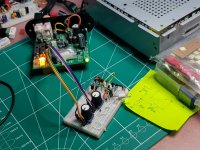
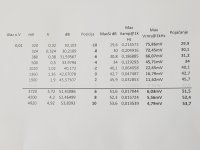
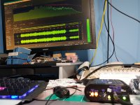
That previous work partially presented in previous post prove to be good mod. That modified ART DJ Pre - II works stable and objectively measured much better then in original configuration. But now I have something even better, observing the position of Gain for my Pioneer Pro-DJ PC-X5 cartridge, which is no other then branded(OEM) AT-3600L i get puzzled why it needs the same ~+4 Gain trim which is like +39-40dB on printed scale, and on the other hand on my made Lab-Preamp (that metal box at my wok bench pics.) measurements shows that it can be put on +34-35dB to get same -1..-3dB signal levels. So I took of little 5k gain pot and find out source of problem is non linear etc. its logarithmic nature of strange applied amplification design.
In short by "fixing" inverse log position of DJ Pre II by switching to 2,5k Lin can get you almost linear selection of gain:
To get beyond +45dB up to that +53.8 gain, you need to disconnect Pot pin 1 and 4 or to bypass then with 100k-1M Ohm.
If you omit those resistors for Pot bypass (left open pin 1-2, 4-5) you will get no more then +53,9dB at the best.
So until my 2k Lin Burns (2 gang - stereo) potentiometer arrives box stays open,
Best regards,
dr Jovan I.
p.s. I hope that someone in ART is reading this posts and is getting attention, because we are giving them free directions how to improve there products.
In short by "fixing" inverse log position of DJ Pre II by switching to 2,5k Lin can get you almost linear selection of gain:
| Bypass | 2K5 Linear potentiometer | Position in % | Ohm | no | Vp-p | Gain "+dB" |
| 1M | Input Vpp=10mV | 0 | 2500 | 0 | 0,56 | 34,96376 |
| 25 | 1 | 0,64 | 36,1236 | |||
| 33,3 | 2 | 0,69 | 36,77698 | |||
| 50 | 1268 | 3 | 0,88 | 38,88965 | ||
| 66,7 | 4 | 1,09 | 40,74853 | |||
| 75 | 5 | 1,88 | 45,48316 | |||
| 100 | 1.25 | 6 | 4,92 | 53,8393 |
If you omit those resistors for Pot bypass (left open pin 1-2, 4-5) you will get no more then +53,9dB at the best.
So until my 2k Lin Burns (2 gang - stereo) potentiometer arrives box stays open,
Best regards,
dr Jovan I.
p.s. I hope that someone in ART is reading this posts and is getting attention, because we are giving them free directions how to improve there products.
Attachments
Just one clarification and little quiz. fist an answer to people who (indirectly) ask my why NJM and not some super-duper AD, TI-OPA, LME (like AD80xx/ADA4871 or OPA21/26/16xx, LM4562/LME497xx) Op.Amp for this Pre-Amp modification. Yes I tried loot of them (almost all known) and scientifically measure all of them in real-time application environment, and only after all of that I rejected all prejudices and choose one that have balanced impact factor of 90% on performance and just 10% price. So for example if OPA1612 is just 11% better I will blindly took them even if it is more then 9x more expensive (and it is).
When someone who has done "sponsored" research and says something like the AD79* OPA2132 or LM4562 is 100x better and suggests you replace your component with another one just so you can buy ie. get a 20x more expensive part with "0" impact, just say "goodbye and a pleasant journey".
And now quiz, for all of you who like to get and swap engineered prefabricated IC Op.Apms for "newer, more modern and forum says better Op. Amps" just by "sound of it name" and by looking at datasheets that was prepared by a producers marketing (not the engineering) department to look super-hyper-fantastic.
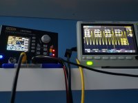
Look on this picture and give me answer what you think, which tested Op-Amp (list of tested is in left-up corner) have which corresponding color line of spectral image? To make it more easy I already mapped TL072CP as last one in "pink".
All Op.Amps are measured with same setup, and environment with BNC-50Ohm terminated canal input, on dedicated 12,6V battery powers supply, while the assembly is placed in a transformer sheet box (better protection against electric and magnetic fields) which was properly grounded. an audio cable ("Taskers C121 2x0.25 Professional Noiseless Audio Cable Low Capacity" was used with profy golden connectors, and setup has:190mO/260pF) routed the resulting amplified signal to an optimized* dedicated sound card. etc.
Take a good look at the picture as some of the answers will surprise you

When someone who has done "sponsored" research and says something like the AD79* OPA2132 or LM4562 is 100x better and suggests you replace your component with another one just so you can buy ie. get a 20x more expensive part with "0" impact, just say "goodbye and a pleasant journey".
And now quiz, for all of you who like to get and swap engineered prefabricated IC Op.Apms for "newer, more modern and forum says better Op. Amps" just by "sound of it name" and by looking at datasheets that was prepared by a producers marketing (not the engineering) department to look super-hyper-fantastic.
Look on this picture and give me answer what you think, which tested Op-Amp (list of tested is in left-up corner) have which corresponding color line of spectral image? To make it more easy I already mapped TL072CP as last one in "pink".
All Op.Amps are measured with same setup, and environment with BNC-50Ohm terminated canal input, on dedicated 12,6V battery powers supply, while the assembly is placed in a transformer sheet box (better protection against electric and magnetic fields) which was properly grounded. an audio cable ("Taskers C121 2x0.25 Professional Noiseless Audio Cable Low Capacity" was used with profy golden connectors, and setup has:190mO/260pF) routed the resulting amplified signal to an optimized* dedicated sound card. etc.
Take a good look at the picture as some of the answers will surprise you
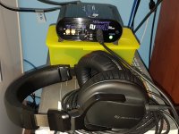
JovanEps, thank you very much for all of that!
I picked up an ART Precision Phono Preamp ($10 more than the DJ and does MC and MM) today in hopes of replacing my old Nikko Beta 30 in use for only it's phono preamp in my home theatre system since my Pioneer VSX-1014 does not have a phono input. It's not my main listening system so thought I'd try a cheap preamp and so far so good. I like the footprint of the ART compared to the Nikko and as far as sound, I like it. My ART has a power switch, the power light on the front is a switch which pleasantly surprised me. The supplied adapter is a 9VAC type and I did try a very good 12VDC adapter with what I believe to be the proper polarity (+ on the center pin) but the unit would not turn on. The filter light shows as on when the DC adapter is plugged in but would not turn on. So I left the supplied AC adapter on it and it works fine. My old worn ears are very happy with this thing and am enjoying the new found space on my equipment stand with the Nikko gone. The only complaint so far is the noise it generates for a second or 2 at turn on and off.
I picked up an ART Precision Phono Preamp ($10 more than the DJ and does MC and MM) today in hopes of replacing my old Nikko Beta 30 in use for only it's phono preamp in my home theatre system since my Pioneer VSX-1014 does not have a phono input. It's not my main listening system so thought I'd try a cheap preamp and so far so good. I like the footprint of the ART compared to the Nikko and as far as sound, I like it. My ART has a power switch, the power light on the front is a switch which pleasantly surprised me. The supplied adapter is a 9VAC type and I did try a very good 12VDC adapter with what I believe to be the proper polarity (+ on the center pin) but the unit would not turn on. The filter light shows as on when the DC adapter is plugged in but would not turn on. So I left the supplied AC adapter on it and it works fine. My old worn ears are very happy with this thing and am enjoying the new found space on my equipment stand with the Nikko gone. The only complaint so far is the noise it generates for a second or 2 at turn on and off.
Greetings Shadow59,JovanEps, thank you very much for all of that!
I picked up an ART Precision Phono Preamp ($10 more than the DJ and does MC and MM) today in hopes of replacing my old Nikko Beta 30 in use for only it's phono preamp in my home theatre system since my Pioneer VSX-1014 does not have a phono input. It's not my main listening system so thought I'd try a cheap preamp and so far so good. I like the footprint of the ART compared to the Nikko and as far as sound, I like it. My ART has a power switch, the power light on the front is a switch which pleasantly surprised me. The supplied adapter is a 9VAC type and I did try a very good 12VDC adapter with what I believe to be the proper polarity (+ on the center pin) but the unit would not turn on. The filter light shows as on when the DC adapter is plugged in but would not turn on. So I left the supplied AC adapter on it and it works fine. My old worn ears are very happy with this thing and am enjoying the new found space on my equipment stand with the Nikko gone. The only complaint so far is the noise it generates for a second or 2 at turn on and off.
unfortunately, I am not familiar with the design details of your preamplifier, but I assume that if it supports MC cartridges, there is another preamplifier block (with +15…20dB), for which only one Op.Amp IC is enough. I assume that because on the ART DJPRE-II I already exceeded the design limit with +54dB gain and without intervention on the Op.Amp original feedback circuit. If my assumption is correct it also means that the preamp works with Op.Amp that are in higher voltage mode due to need for a better signal-to-noise ratio. With higher working voltage range, it easier to achieve the desired characteristic SNR at +60…+65dB which is desirable for MC cartridges. This all means that it is likely that the 9V AC (RMS on full load) is better filtered after rectification and after all the losses in the diode bridge and in the linear regulator it still gives a solid ~15V DC.
Well, I assume that the 12VDC that you brought to its input is after the losses on the diodes and the linear regulator (and if there is no conversion) giving it less than 9VDC, and that is not sufficient to power the components and that is the reason why the OP Amps are not activated. I assume that those OP-Amps have Vmin greater than +/-4.5V, ie. 9V on a single supply.
If I knew exactly what is on the circuit board of your device, I would be able to tell you more.
And if my assumption is correct, your device could probably work without problems already at 13.5V DC, since it will lose about 2-2.5V to the output of the rectifier block.
I recommend you not to worry too much and continue to use its original supplied AC power supply.
I see that I haven't updated the status of my modification work, so let me give you the last update.
On the ART-DJ-PRE-II I modified the following:
- The old 5k Log Potentiometer was retained but I separated pins 1 and 4 from the existing line and bridged that connection with a 1M resistor with the addition of a 100pF NP0 capacitor between pins 1-2 and 4-5. In this way, I released the potential to get +54dB of gain, and I managed to suppress (LPF) the higher frequencies outside the audible range with the reservation that at least the 2nd harmonic of the sound at 16kHz can appear without loss (illustration below).
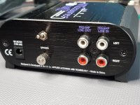
- I then added a 3.5mm stereo banana connector (metal shielded), which is tied to the output using a shielded separate Tasker C121 2x0.25 cable.
I thought about adding the logic for the XLR connector and installing it, but unfortunately, I'm running out of space in the case itself, and I don't need it at the moment, so I don't want to complicate it. I also gave up on the idea of installing an ADC with the addition of a BT controller, which would enable wireless streaming, since as far as I know such a solution already exists in the DJ-Pre-II version.
I am currently working on my own solution for a +60dB Phono Pre. Amp. which in its current design achieves a FOM to RIAA as high as 65105, which means that the deviation from the RIAA defined curve at any point is less than 0.01dB. Of course, this implies the use of a passive RIAA network, which is at the optimum limit of -22dB with manually matched components. For now, even if it's only in the protoboard phase, the results obtained are fantastic, but more on that in another place and some other time.
Best regards,
dr Jovan I.
p.s. If you need expert help taking your devices to the next level, I'd be happy to help, so feel free to call.
On the ART-DJ-PRE-II I modified the following:
- The old 5k Log Potentiometer was retained but I separated pins 1 and 4 from the existing line and bridged that connection with a 1M resistor with the addition of a 100pF NP0 capacitor between pins 1-2 and 4-5. In this way, I released the potential to get +54dB of gain, and I managed to suppress (LPF) the higher frequencies outside the audible range with the reservation that at least the 2nd harmonic of the sound at 16kHz can appear without loss (illustration below).
- I then added a 3.5mm stereo banana connector (metal shielded), which is tied to the output using a shielded separate Tasker C121 2x0.25 cable.
I thought about adding the logic for the XLR connector and installing it, but unfortunately, I'm running out of space in the case itself, and I don't need it at the moment, so I don't want to complicate it. I also gave up on the idea of installing an ADC with the addition of a BT controller, which would enable wireless streaming, since as far as I know such a solution already exists in the DJ-Pre-II version.
I am currently working on my own solution for a +60dB Phono Pre. Amp. which in its current design achieves a FOM to RIAA as high as 65105, which means that the deviation from the RIAA defined curve at any point is less than 0.01dB. Of course, this implies the use of a passive RIAA network, which is at the optimum limit of -22dB with manually matched components. For now, even if it's only in the protoboard phase, the results obtained are fantastic, but more on that in another place and some other time.
Best regards,
dr Jovan I.
p.s. If you need expert help taking your devices to the next level, I'd be happy to help, so feel free to call.
Attachments
-
 20221025_003034.jpg359.7 KB · Views: 183
 -
 20221030_104954.jpg450.3 KB · Views: 155
 -
 20221030_105009.jpg465.6 KB · Views: 143
 -
 20221030_105203.jpg293.8 KB · Views: 143
 -
 20221110_201402.jpg451.8 KB · Views: 135
 -
 20221110_201417.jpg403.5 KB · Views: 214
 -
 20220930_234944.jpg546.3 KB · Views: 192
 -
 20220930_235415.jpg444.8 KB · Views: 159
 -
 20221001_010220.jpg342.4 KB · Views: 150
 -
 20221025_002348.jpg466 KB · Views: 170
 -
 20221027_222629.jpg593.9 KB · Views: 175
 -
 20221027_222700.jpg353.2 KB · Views: 186
- Home
- Source & Line
- Analogue Source
- Art Djpre II Modifications