Looking at the ZTX689B, one can see in the image below that the hfe at Ic=5.5mA will be reduced from 500 to the same level as the ZTX851.
I'm not seeing that in those curves.
Looking at the 25 deg C curves the hFE of the ZTX689 doesn't go below 700 (typ) at any plotted current below 100 mA. At -55 deg C hFE 400 is the minimum. 5.5 MA looks to be just shy of an hFE of 900 at 25 deg.
The ZTX851 curve never goes above 200 (typ) at any current. I think the highest gain ZTX851 I've seen (200 uA test current) is about 220. 140-180 is the typical distribution.
The limited number of ZTX689B I've tested ranged from 450-650 at 200 uA test current.
I have said elsewhere that the ZTX689 would be better-suited as a mic preamp front-end rather than an MC preamp due to the higher source impedance. The difference in rbb is less noticeable and the higher gain a possible advantage.
Silly mistake, I was only a factor 1000 wrongI'm not seeing that in those curves.
Looking at the 25 deg C curves the hFE of the ZTX689 doesn't go below 700 (typ) at any plotted current below 100 mA. At -55 deg C hFE 400 is the minimum. 5.5 MA looks to be just shy of an hFE of 900 at 25 deg.
The ZTX851 curve never goes above 200 (typ) at any current. I think the highest gain ZTX851 I've seen (200 uA test current) is about 220. 140-180 is the typical distribution.
The limited number of ZTX689B I've tested ranged from 450-650 at 200 uA test current.
I have said elsewhere that the ZTX689 would be better-suited as a mic preamp front-end rather than an MC preamp due to the higher source impedance. The difference in rbb is less noticeable and the higher gain a possible advantage.

It's easy to forget that these are power transistors designed for florescent emergency lighting and auto horn bridge drivers.
At least the +6dB noise increase was correct with Ic = 1mA.
In situations allowing for this higher noise, input current is ca. 25 times lower as with the ZTX851 at 5.5 mA.
Very interesting.
Hans
I’m still thinking what to do.
Either box the Head Amp and leave it in place, or modify my MC amp from Voltage to Current.
But I tend to prefer to keep the Head Amp and reduce its gain to restore some of the lost 16dB overload margin in the MC phono-amp.
That may be the best and most flexible solution.
Hans
Back from the ZTX689B to your headamp. Have you decided on a way to reduce the gain of the transimpedance amp? I would rather follow your lead on that than try to come up with a solution myself.
Oh yes of course.Back from the ZTX689B to your headamp. Have you decided on a way to reduce the gain of the transimpedance amp? I would rather follow your lead on that than try to come up with a solution myself.
As you may have noticed in the specifications, gain can be chosen from 4 settings, 50R/Rcart, 100R/Rcart, 200R/Rcart and 400R/Rcart.
In my case, with a 34R cart, I initially had setting nr 3 or 200R/34R = 15dB.
Since this reduced the OL marging of the MC Phonoamp following this Head Amp too much, I went to setting nr2 or 100R/34 = 9dB.
Since I noticed no further negative effects of this lower gain setting on the reproduced sound, this is how I'm using the HA now.
OL marging of my MC Phonoamp was >33dB ref 0.5mV@1kHz/5cm/sec from 20Hz to 20kHz, has now been reduced by 9dB or to 24dB ref 0.5mV.
Not as good as it was, but still fully acceptable.
Hans
Attachments
Yes, I've considered reducing the gain of my MC phonoamp, but since the 9dB setting worked so well, I kept everything intact for the time being.I thought you might want to make the change elsewhere in the circuit. I have one MC cartridge with 5R cart with a loading specification >10R. I would be looking to load it with 15R for roughly 9dB of gain. Do you foresee any problems with that?
As for your 5R Cart, loading is always 0R with a transimpedance amp, no matter what gain you would prefer.
With 15R/5R this would result in 9.5dB gain, resulting in two 7R5 feedback resistors for this very amp.
I've tested successfully with 25R feedback resistors, but my feeling is that 7R5 would be too much asked for the LT6203.
So before suggesting you a possible solution, may I ask you some details:
- What is the specified output of your 5R cart at 5cm/sec@1Khz
- Do you envisage to use the HA's Diff or the SE output
- What are the specs of your phonoamp receiving the HA's output signal like: sensitivity, gain, noise, OL margin and highest load impedance setting.
Hans
I might just not use this particular cartridge with your transimpedance version, but here is some of the information for a start. I will almost certainly just use a Denon DL-103R with 14R. I really enjoy the Denon anyway.
Output voltage at 1000 Hz, 5cm/sec. - 0.34 mV
Internal impedance, DC resistance - 5 Ohm
I have a choice of either a DIFF or SE connected phonoamp.
For the SE MC phonoamp: gain 75dB / 71dB / 65dB / 61dB selectable without making changes with a soldering iron. Input impedance 5R - 47k. OL margin with this cartridge and the 9.5dB headamp gain almost exactly 22dB. Noise -81 dB ref. 1 mV input.
I could of course also try to use a SE MM phonoamp with 40dB of gain.
I don't have all the information of the Bal/Diff MC phonostage handy.
Thank you for your infos.I might just not use this particular cartridge with your transimpedance version, but here is some of the information for a start. I will almost certainly just use a Denon DL-103R with 14R. I really enjoy the Denon anyway.
Output voltage at 1000 Hz, 5cm/sec. - 0.34 mV
Internal impedance, DC resistance - 5 Ohm
I have a choice of either a DIFF or SE connected phonoamp.
For the SE MC phonoamp: gain 75dB / 71dB / 65dB / 61dB selectable without making changes with a soldering iron. Input impedance 5R - 47k. OL margin with this cartridge and the 9.5dB headamp gain almost exactly 22dB. Noise -81 dB ref. 1 mV input.
I could of course also try to use a SE MM phonoamp with 40dB of gain.
I don't have all the information of the Bal/Diff MC phonostage handy.
When you have the choice of using a MM phonoamp, this is to be preferered, because the HA can be given a substantial gain like 30dB with the 400R/14 for the Denon DL-103 or 200R/5 for your other 5R Cart.
Having a low gain with a very low ohmic Cart, would mean very low ohmic feedback resistors, which is not a good idea as already explained.
But of course for your Denon you could also use the 50R/14 setting to get 11dB gain in combination with a 61dB/47K MC phonoamp.
So in your case for the Denon, you could try either the MC or the MM phonoamp by just switching the straps from pos 1 to pos 4 and listen what sound you prefer if any.
Hans
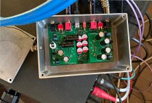
I just noticed R1 and R2 on the mainboard in the photo above [#227]. I've never seen parts like that. What are those?
As with the two electrolytic caps lying horizontally and the sockets for two ZTX transistors, this amp is the prototype for the final version.
R1 and R2 were paralleled with two diodes as test to accelerate power on, but since this did not bring any improvement and they do no harm, I just left them so please don't pay it any attention.
Hans
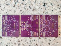
I have reached the point of no return on this project. The initial three transimpedance amp boards arrived in the mail today. I didn't order the main boards yet, because I switched to a new supplier and wanted to see their results first. They look good to me so far.
Attachments
I have reached the point of no return on this project. The initial three transimpedance amp boards arrived in the mail today. I didn't order the main boards yet, because I switched to a new supplier and wanted to see their results first. They look good to me so far.
Looking great,
Succes
Hans
..... 1) The two emitter resistances have been removed, resulting in less noise. The reason they were there in the first place was to relax the Vbe differences between the two input transistors. But because U1, the LT1884 takes fully care of correcting these differences, we no longer need them .....
Hans
Does the transimpedance amp benefit in any way from matching the input transistors after this change - within each pair and/or between the two pairs?
Hans
Does the transimpedance amp benefit in any way from matching the input transistors after this change - within each pair and/or between the two pairs?
Hans
I started with matched transistors, but after having socketed one pair, I could plug in any non matched transistor without any effect on noise or input offset voltage.
Differences are completely corrected by the servo.
At the same time my experience was that all transistors from various batches where quite close within a few mV Vbe.
Hans
Update on previous information, with pictures added to the Dropbox link.
This universal Diff In / Diff or SE Out Head Amp, as its name suggest, can be used in many ways to amplify the signal from almost every MC Cart, both as a Voltage Amplifier but also as a Current Amplifier.
With its independent power supply and low output impedance, the Head-Amp can be used to steer a high quality 47K MM phono amp, but also a DSP without having to use its Phantom supply.
When having changed to a new very low output MC Cart, the Universal Head Amp can also be used between this new Cart and the existing MC phonoamp.
For power supply, a small 10A/hr Power Bank has enough energy for 300 hrs of operation between reloads, but also a 5Watt USB mains adapter can be used.
Equivalent Input Noise
Noise RTI for the bare low noise Head amp module
Ein Flat: <310pV/rtHz
Ein after A-weighting and Riaa correction:<140pV/rtHz.
S/N including Cart,
A-Weighted and after Riaa using a 5nV/rtHz Riaa Phono amp RTI.
>78dB-A for 5-40 Ohm Carts producing 0.5mV@5cm/sec@1Khz
>75dB-A for 2-10 Ohm Carts producing 0.2mV@5cm/sec@1kHz
>72dB-A for 1-5 Ohm Carts producing 0.1mV@5cm/sec@1Khz
CMRR
>50dB when using the components as advised.
High impedance Voltage Module
Rin: 260 Ohm
Four Gain settings +/- 0.5dB depending on Rcart of resp: 33dB, 27dB, 22dB and 16dB +/- easily selectable with one Jumper Socket
Current Module
Rin: Virtual Gnd
Four Gain settings of resp: 50R/Rcart, 100R/Rcart, 200R/Rcart and 400R/Rcart, selectable with 2 Jumper Sockets, to be moved simultaneous.
Output
Balanced Differential output impedance 44 Ohm, or
Single Ended output impedance 22 Ohm, selectable by switch.
Distortion ≤ 0.01%@100mV rms out from 20Hz to 20Khz.
1% distortion at 800 mV rms out
Power Supply
5 Volt USB power to be connected through mini B USB on board socket.
Supply current 25 mA. Can either be a smart phone Power Bank, or a 5W USB Wall Wart.
When using a Power Bank, extra load may have to be added to prevent the Power Bank from going into idle.
Gerbers etc
I don’t want to be involved in any form of production, but Gerbers, Boms, Circuit Diagrams and Pictures are available from here:
Dropbox - Zip Files Head Amp - Simplify your life
Hans
P.S.1 With my Cart, I very much preferred the sound of the Transimpedance amp
P.S.2 This design is not for the unexperienced DIY.
Several SOT23 circuits have been used, having the size of 1/4 of a DIP.
- Status
- This old topic is closed. If you want to reopen this topic, contact a moderator using the "Report Post" button.
- Home
- Source & Line
- Analogue Source
- Designing a universal diff-in/diff-out Head Amp