Hans, if you were going to box this up how would you do the grounding? For normal balanced operation there would be a STP cable from the tonearm with +/- connected and the screen as 'pin1' straight to the box with same on the output. The Nokia wall wart is not connected to PE (if it's anything like the ones I have) so it is floating as would be on battery? Is this howyou would do it?
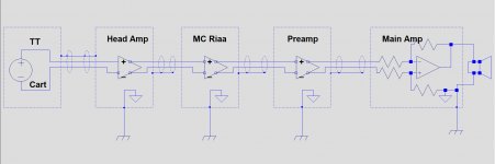
Bill,in the image below I have tried to sketch how I connect my equipment.Hans, if you were going to box this up how would you do the grounding? For normal balanced operation there would be a STP cable from the tonearm with +/- connected and the screen as 'pin1' straight to the box with same on the output. The Nokia wall wart is not connected to PE (if it's anything like the ones I have) so it is floating as would be on battery? Is this howyou would do it?
Every individual part is diff-in / diff-out.
Since you only need two wires to transfer a signal and not three, Pin 1 on the receiving side is not connected and every box is individually connected to mains gnd.
This way of connecting, called OEO (for one end only), prevents ground loops and equalisation currents between the different chassis, since the chassis all have slightly different voltages with different pollution.
The CMRR of all modules are well able to suppress these differences.
As a matter of fact, at this very moment, the Head Amp is not even connected to Mains Earth and is fully floating, but no sign of any 50Hz hum with the Power Bank or with the Wal Wart.
But when I have finalised my listening tests, I will pay some attention to this aspect, because the output can also be switched to SE.
In that case the Head Amp box will automatically be connected to the box of the MM amp. In Case of using a DSP, the differential connection is to be preferred.
Hans
.
Attachments
Interesting, thanks Hans. I asked becuaseI will be in a position where turntable and preamp are floating and if I use Optical out from the ADC has no change of being connected to ground unless I decide to. Opens up some options as do not need to worry about a PE connection.
The universal Head Amp, as its name suggest, can be used in many ways to amplify the signal from almost every MC Cart, both as a Voltage Amplifier but also as a Current Amplifier.
With its independent power supply and low output impedance, the Head-Amp can be used to steer a high quality 47K MM phono amp, but also a DSP without having to use its Phantom supply.
When having changed to a very low output MC Cart, the Universal Head Amp can also be used between the new Cart and the existing MC phonoamp.
For power supply, a small 10A/hr Power Bank has enough energy for 300 hrs of operation between reloads, but also a 5Watt USB mains adapter can be used.
Noise RTI for the bare low noise Diff Head amp module
En: <250pV/rtHz
High impedance Voltage Module
Rin: 260 Ohm
Four Gain settings +/- 0.5dB depending on Rcart of resp: 33dB, 27dB, 22dB and 16dB +/- easily selectable with a Jumper Socket
Current Module
Rin: Virtual Gnd
Four Gain settings of resp: 50R/Rcart, 100R/Rcart, 200R/Rcart and 400R/Rcart, selectable with 2 Jumper Sockets, to be moved simultaneous.
Output
Balanced Differential output impedance 44 Ohm, or
Single Ended output impedance 22 Ohm, selectable by switch.
Distortion ≤ 0.01%@100mV rms out from 20Hz to 20Khz.
1% distortion at 800 mV rms out
S/N including Cart,
A-Weighted and after Riaa using a 5nV/rtHz Riaa Phono amp RTI.
>78dB-A for 5-40 Ohm Carts producing 0.5mV@5cm/sec@1Khz
>75dB-A for 2-10 Ohm Carts producing 0.2mV@5cm/sec@1kHz
>72dB-A for 1-5 Ohm Carts producing 0.1mV@5cm/sec@1Khz
CMRR
>50dB when using the components as advised.
Power Supply
5 Volt USB power to be connected through mini B USB on board socket.
Supply current 25 mA. Can either be a smart phone Power Bank, or a 5W USB Wall Wart.
When using a Power Bank, extra load may have to be added to prevent the Power Bank from going into idle.
Gerbers etc
I don’t want to be involved in any form of production, but Gerbers, Boms and circuit diagrams are available from here:
Dropbox - Zip Files - Simplify your life
Hans
P.S. The results of the listening tests and the sound differences between the two different topologies will be published after careful listening.
I don't want to jump to conclusions.
P.S.2 This design is not for the unexperienced DIY. Several SOT23 circuits have been used, having the size of 1/4 of a DIP.
Last edited:
Rick, thanks for your comment.This is some really beautiful work!
Is the signal polarity flipped on the Transimpedance form?
Also, am having a hard time understanding how 12-bit hardware is producing -190 dBxx, whether dBFS, dBV, dBu, or something else. Probably just a shortage of bits in my brain, though.
Still, great stuff -- and thanks for publishing.
Rick
About capturing -190dB with 12 bits, this can only be done when noise of the measurement equipment lies well below this level.
Twelve bits roughly means a dynamic range of 72 dB, or for my scope from 3uV to 10mV
To make 250pV visible, you have to amplify the signal at least 12.000 times or 72dB to bring it at this 3uV level.
That’s what I did with the Head Amp’s 34dB gain plus a very low noise 60dB amplifier in between.
Hans
P.s. Averaging the FFT spectra at least 40 times, which is what I did, gives another gain in sensitivity of sqrt(40), or 32dB
Last edited:
I thought that I had one of the best MC preamps around, but after quite some hours of listening, I hate it to admit that the transimpedance or current amp still improves on that.
Instruments and voices are more isolated from the background, closer to the listener, warmer and with more substance but at the same time very sparkling without sharpness
It just sounds more real.
But the thing that convinced me at the end was the fact that the sound is less fatiguing after having used to the new sound.
I have to stipulate that this is true for my audio set, and cannot be seen as a guarantee for other systems.
Hans
I half expected that. Will be interested if getting it in a box changes anything.
I’m still thinking what to do.
Either box the Head Amp and leave it in place, or modify my MC amp from Voltage to Current.
But I tend to prefer to keep the Head Amp and reduce its gain to restore some of the lost 16dB overload margin in the MC phono-amp.
That may be the best and most flexible solution.
Hans
Having had quite some time listening to the Transimpedance Head Amp, around 100 LP's, I came to the next conclusion that I wanted to share.
Although there is no measurable difference between Power Bank or Wall Wart, there is quite some difference in listening experience.
Sound with the mains adapter is a bit chill and analytical, whereas the sound with the Power Bank, a clear winner, is a warm and involving.
You make shake your head in disbelief or start thinking about DBLT, but that's how it is for me.
Fortunately both ways of supplying are easy to try with no hardware change or whatever, so let everybody be his own judge.
Hans
P.S. in #204 I mentioned a Noise RTI (Referred To Input) of <250pV/rtHz for the bare amp module. I repeated the calculation and came to a slightly higher figure of circa 310pV/rtHz equivalent to a 5.8R resistor.
The rest of the figures will remain unaffected.
In practice this will hardly have any impact since this value of 5.8R after Riaa and A-weighting becomes the equivalent of 0.95R or 126pV/rtHz or 17.8nV from 20Hz to 20Khz.
So when having a 1R Cart producing 0.1mV@5cm/sec@1kHz, S/N will be 20*log(0.1mV/17.8nV) = 75dBA.
This figure will be reduced 1 or 2dB depending on the quality of the MM Riaa amp connected to the Head Amp, but it shows that with the 310pV/rtHz everything is still well under control.
Thank you for your friendly words.Hans,
Your current amp is such a terrific design that I expected way more interest in building it than I've seen in this thread. I have 90% of the parts already and I can't wait to get started.
Hans
Hans - Remember this sim? A Low Noise Balanced Input Moving Coil Preamp Using the ZTX851 - Page 44 - Pro Audio Design Forum
Would you mind running it again and increasing rbb for both transistors until it becomes 2.7 dB noisier?
That's the approximate noise increase switching from a ZTX851 to the higher gain ZTX689B.
I'd like to confrim my rbb estimates. The ZTX689B (and ZTX789A PNP) will make good mic preamp input transistors.
Thanks in advance - Wayne.
EDIT:
The ZTX689 measures around 0.6nV√Hz flat...
Would you mind running it again and increasing rbb for both transistors until it becomes 2.7 dB noisier?
That's the approximate noise increase switching from a ZTX851 to the higher gain ZTX689B.
I'd like to confrim my rbb estimates. The ZTX689B (and ZTX789A PNP) will make good mic preamp input transistors.
Thanks in advance - Wayne.
EDIT:
So for 0.32nV/rtHz equivalent input noise, you only need a Head Amp with a flat equivalent input noise of 0.64nV/rtHz.
The ZTX689 measures around 0.6nV√Hz flat...
Last edited:
Hi Wayne,Hans - Remember this sim? A Low Noise Balanced Input Moving Coil Preamp Using the ZTX851 - Page 44 - Pro Audio Design Forum
Would you mind running it again and increasing rbb for both transistors until it becomes 2.7 dB noisier?
That's the approximate noise increase switching from a ZTX851 to the higher gain ZTX689B.
I'd like to confrim my rbb estimates. The ZTX689B (and ZTX789A PNP) will make good mic preamp input transistors.
Thanks in advance - Wayne.
EDIT:
The ZTX689 measures around 0.6nV√Hz flat...
Sorry I missed your posting.
Will produce an answer pretty soon.
Hans
Wayne,Hans - Remember this sim? A Low Noise Balanced Input Moving Coil Preamp Using the ZTX851 - Page 44 - Pro Audio Design Forum
Would you mind running it again and increasing rbb for both transistors until it becomes 2.7 dB noisier?
That's the approximate noise increase switching from a ZTX851 to the higher gain ZTX689B.
I'd like to confrim my rbb estimates. The ZTX689B (and ZTX789A PNP) will make good mic preamp input transistors.
Thanks in advance - Wayne.
EDIT:
The ZTX689 measures around 0.6nV√Hz flat...
I have calculated the input noise of your amp with Rg=1R and Rcart=10R with an Rb of 1.5R
After subtracting the noise from Rg+Rcart=11R I got 55.5nV RTI from 20Hz to 20Khz for the bare amp.
2.7 extra noise means an increase to 75.5nV RTI from 20Hz to 20Khz.
I had to raise the Rb in my ZTX81 model from 1.5R to 5.3R to achieve this target.
I hope this is what you had in mind with your question.
Hans
(corrected part number typo)I had to raise the Rb in my ZTX851 model from 1.5R to 5.3R to achieve this target.
Thanks Hans. That was pretty close to my guestimate based on working backwards form the noise measurements.
Looks like we have another winner in the ZTX689B. (And ZTX789A.)
(corrected part number typo)
Thanks Hans. That was pretty close to my guestimate based on working backwards form the noise measurements.
Looks like we have another winner in the ZTX689B. (And ZTX789A.)
This is only part of the story.
Looking at the ZTX689B, one can see in the image below that the hfe at Ic=5.5mA will be reduced from 500 to the same level as the ZTX851.
This implies that when wanting to take profit of the high hfe, Ic must be reduced to 1mA.
This has an adverse effect on the noise, because the 1/2gm noise component goes from 2.3R to 12.5R.
I have simulated again with Rb=5.3R but now with Ic=1mA for the ZTX689B.
The effect is a 6.2dB raise in noise compared to your ZTX851 design running at 5.5mA.
Hans

- Status
- This old topic is closed. If you want to reopen this topic, contact a moderator using the "Report Post" button.
- Home
- Source & Line
- Analogue Source
- Designing a universal diff-in/diff-out Head Amp