Hi Philipe,Hi all of you,
As I'm building 2 TT's with a carbonfiber tonearm of 75mm and I like the idea off a "prépré-amp" in SMD (as in #150 by Hans) mounted on top of the headshell. Would the LSK389 in SOIC 8L be a good combination?
Philippe
That seems to be a perfect Fet for the puropse, but maybe a bit difficult to find.
The other thing is that you end up with 6 wires from the headshell instead of 4.
When that's not a problem, I wish you all the fun in building and listening to the prépré-amp.
Hans
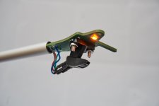
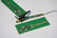
I found this on another site yesterday. Whilst I am not convinced that FR4 is a good headshell material I do like the packaging.
Looks like some castrated 8-legs there, 5 left OUCH!
I'm in awe of some of the contributions & contributors on this thread that Han's linked to from the Ultra low noise thread ... so with fear & trepidation ... I humbly present these active ribbon designs more as ideas for P48V MC amps rather than finished designs. There are caveats, as they stand, for '30R' ribbon transformers .. let alone 5R MC cartridges.
The first has not been tried. 2x7mA is beyond the optimum current for even ZTX851 though 2 pairs will do nicely.
The second is in a commercial product. This runs 2x2.43mA for ye Olde Unobtainium Shoppe devices available (?) at the time. Today, I would use 2xZTX851 at 2x5mA
I still have reservations about ribbon protection but there have not been any adverse reports yet. (fingers crossed).
Subsonic response is yucky but most mike preamps seem to have an appropriate LF roll-off that saves us embarrassement
There is no good way to adjust input offset so the devices have to be matched for Vbe at the working current and epoxy encapsulated ala Wayne Kirkwood in a nut.
I'm sorry these poor efforts do not have zillion bits but those beasts are well beyond the ken of my small brain.
Attachments
After having followed various threads on the same head amp topic, I have finally decided to put things in practice.
The design is still based on the ideas in #4 of this thread, with a few changes, such as:
1) The two emitter resistances have been removed, resulting in less noise.
The reason they were there in the first place was to relax the Vbe differences between the two input transistors.
But because U1, the LT1884 takes fully care of correcting these differences, we no longer need them
2) I originally used an active element to control the positive supply voltage for the PNP transistor.
But since U1 can supply this 3mA supply current with ease, there is no need for an extra active element.
Apart from some difference in component values, the design is still intact.
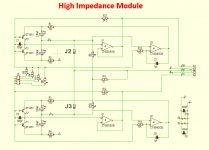
With this amplifier module, it is possible to create a Virtual Earth inverting head amp as well as a more usual High Impedance non inverting amp.
However, because it would take many jumpers to switch from one topology into another, I have chosen for a univeral mother board, with easy switchable piggy back modules.
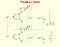
That's why I have made separate Virtual Earth and a High Impedance modules, configured as diff in / diff out, as shown in #5 of this thread.
Now you can compare Virt. Earth input to High Impedance input with one and the same amp, which will make this solution quite unique.
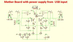
I struggled quite some time with a power supply to be universal in combination with an MM preamp but also in combination with a DSP and finally decided on a 5 Volt powerbank such as used for Smart-phones.
They offer a cheap very low noise power solution, can be easily charged from the mains, but with 5000mA will last some 200hrs between charging.
For that reason the main board only has a MiniB USB input socket.
Possibly this input can also be used for a wall wart supply with 5V mini USB output, largely depending on wether the amount of additional noise wil be tolerable.
The high impedance module has 4 preset gain settings, resp 50x, 25x, 12.5x and 6.25x, which can of course be altered by changing resistors.
The virt. earth input version also has 4 preset gain settings, that should be adequate for most carts from 1 Ohm to 50 Ohm with outputs from 0.1mV to 0.5mV@5cm/sec@1Khz.
Noise design goal in this differential topology is 350nV/rtHz, which should be adequate for the most demanding Carts.
Circuit diagrams for the mother board and the two Inv and Non Inv modules are below.
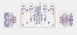
A view on the PCB population is also added.
Hans
The design is still based on the ideas in #4 of this thread, with a few changes, such as:
1) The two emitter resistances have been removed, resulting in less noise.
The reason they were there in the first place was to relax the Vbe differences between the two input transistors.
But because U1, the LT1884 takes fully care of correcting these differences, we no longer need them
2) I originally used an active element to control the positive supply voltage for the PNP transistor.
But since U1 can supply this 3mA supply current with ease, there is no need for an extra active element.
Apart from some difference in component values, the design is still intact.
With this amplifier module, it is possible to create a Virtual Earth inverting head amp as well as a more usual High Impedance non inverting amp.
However, because it would take many jumpers to switch from one topology into another, I have chosen for a univeral mother board, with easy switchable piggy back modules.
That's why I have made separate Virtual Earth and a High Impedance modules, configured as diff in / diff out, as shown in #5 of this thread.
Now you can compare Virt. Earth input to High Impedance input with one and the same amp, which will make this solution quite unique.
I struggled quite some time with a power supply to be universal in combination with an MM preamp but also in combination with a DSP and finally decided on a 5 Volt powerbank such as used for Smart-phones.
They offer a cheap very low noise power solution, can be easily charged from the mains, but with 5000mA will last some 200hrs between charging.
For that reason the main board only has a MiniB USB input socket.
Possibly this input can also be used for a wall wart supply with 5V mini USB output, largely depending on wether the amount of additional noise wil be tolerable.
The high impedance module has 4 preset gain settings, resp 50x, 25x, 12.5x and 6.25x, which can of course be altered by changing resistors.
The virt. earth input version also has 4 preset gain settings, that should be adequate for most carts from 1 Ohm to 50 Ohm with outputs from 0.1mV to 0.5mV@5cm/sec@1Khz.
Noise design goal in this differential topology is 350nV/rtHz, which should be adequate for the most demanding Carts.
Circuit diagrams for the mother board and the two Inv and Non Inv modules are below.
A view on the PCB population is also added.
Hans
Attachments
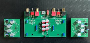
Here a first picture of the ready made modules. To the left a transimpedance amp, in the middle the mother board and to the right a voltage amp. Except from a silly twist in one connector from mother board to piggy back module, a first check shows that everything seems to work properly.
By the addition of a selectable Diff or SE output, the Universal Head Amp is now even more universal. See both switches between the RCA sockets and the Diff to SE converter behind. Input is still differential, since a Cart is a balanced source as long as both coil connections float with respect to signal- and to chassis-ground. A differential topology was chosen in the first place to get a high CMRR and low harmonics from this Head Amp.
Power supply is through a mini B USB input in the middle of the mother board, coming either from a smart phone Power-Bank, or if suppression of pollution is high enough, from a Wall Wart with USB output. Suffice to say that each power bank usually has a direct mains-input to reload the batteries which makes this the preferred choice. To monitor the power supply , I have also added a small warning led D2 on the other side of the mother board that turns on when the supply drops below 4.75 Volt.
Next step will be to measure the noise RTI and to compare this with the sims and last but not least, listen to the two different principles, transimpedance and voltage amps to find out whether any difference in sound reproduction can be noticed. As far as I know for the first time with exactly the same basic amplifier module and the same everything else.
Hans
Attachments
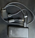
I noticed with my Power Bank, see picture below, that it turns off after a few seconds when the supplied current falls somewhere below 50mA. For that reason I have added a 100 Ohm resistor over 5V input. Total current consumption is now ca. 75mA. With 10Ahr, there is still more than 100hrs of power available, nothing to worry about.
Hans
Hans
Attachments
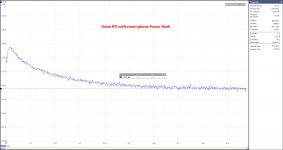
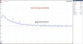
Here some noise measurement results from the transimpedance amp version. Configuration as used was with 1R input resistance, simulating Rcart and with a Gain of 50 or 34 dB.
Not to have any foldback from the 1Mhz 60dB amp in the FR, I used ca 2Mio samples in a 1.07sec window, giving almost a 1Hz bin width, or more exactly 0.93Hz. This means a neglectable error of only 0.3dB when regarding the graphs below to have exactly dBV/rt(1Hz) = dBV on the Y axis.
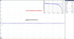
I used a 60dB amp between the Head Amp and the Scope, that added a virtual 26pV/rtHz to the input of the Head Amp (-211.6dBV) when its output noise with short circuited input was divided by 34+60 = 94dB. Noise from this 60dB amp does therefore not contribute to the measured results from the Head Amp.
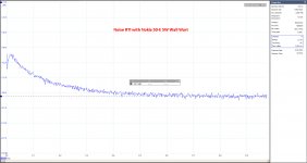
I tried different supplies, resp. a Power Bank, an Apple 10W Wall Wart and a 5W Nokia Wall Wart. Only with the Apple adapter there where mains related harmonics visible, that where not there with the Power Bank and with the Nokia. Below 500Hz, the Nokia even had a few dB less noise as the Power Bank, but that may be caused by a Power Bank that was not fully charged.
As can be seen, noise above 600Hz is -190.7dB or the equivalent of 292pV/rtHz. When correcting for the 1R input resistance, the amp itself produces 262pV/rtHz, quite nice for a differential Head Amp.
Hans
P.S. More to follow on the Voltage Amp version.
Not to have any foldback from the 1Mhz 60dB amp in the FR, I used ca 2Mio samples in a 1.07sec window, giving almost a 1Hz bin width, or more exactly 0.93Hz. This means a neglectable error of only 0.3dB when regarding the graphs below to have exactly dBV/rt(1Hz) = dBV on the Y axis.
I used a 60dB amp between the Head Amp and the Scope, that added a virtual 26pV/rtHz to the input of the Head Amp (-211.6dBV) when its output noise with short circuited input was divided by 34+60 = 94dB. Noise from this 60dB amp does therefore not contribute to the measured results from the Head Amp.
I tried different supplies, resp. a Power Bank, an Apple 10W Wall Wart and a 5W Nokia Wall Wart. Only with the Apple adapter there where mains related harmonics visible, that where not there with the Power Bank and with the Nokia. Below 500Hz, the Nokia even had a few dB less noise as the Power Bank, but that may be caused by a Power Bank that was not fully charged.
As can be seen, noise above 600Hz is -190.7dB or the equivalent of 292pV/rtHz. When correcting for the 1R input resistance, the amp itself produces 262pV/rtHz, quite nice for a differential Head Amp.
Hans
P.S. More to follow on the Voltage Amp version.
Attachments
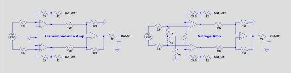
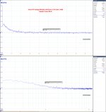
Having now also measured the noise RTI of the voltage amp, something peculiar is visible between the transimpedance and the voltage topologies.
For a clear understanding of what I did, the first image below shows the two topologies, both using the same amp module.
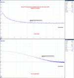
Second image shows the Transimpedance Amp's noise spectrum with a linear horizontal scale as well as with a logarithmic scale. On the logarithmic version, noise below 600 Hz can be seen to have a slope of ca. -30dB/decade. Exactly this same slope is visible in Syn08 image in #403, see here Richard Lee's Ultra low Noise MC Head Amp.
However for the voltage Amp, using the same amplifier module, the raised LF noise spectrum stops at a much lower frequency of ca 200Hz and has a slope of ca. -20dB/dec, see the third image for that.
I practice this has probably hardly any impact, but from a technical point of view I wonder why a virtual gnd topology produces a different pattern as a voltage amp. In this case LT Spice is of no help, because both topologies show the same noise spectrum.
Hans
For a clear understanding of what I did, the first image below shows the two topologies, both using the same amp module.
Second image shows the Transimpedance Amp's noise spectrum with a linear horizontal scale as well as with a logarithmic scale. On the logarithmic version, noise below 600 Hz can be seen to have a slope of ca. -30dB/decade. Exactly this same slope is visible in Syn08 image in #403, see here Richard Lee's Ultra low Noise MC Head Amp.
However for the voltage Amp, using the same amplifier module, the raised LF noise spectrum stops at a much lower frequency of ca 200Hz and has a slope of ca. -20dB/dec, see the third image for that.
I practice this has probably hardly any impact, but from a technical point of view I wonder why a virtual gnd topology produces a different pattern as a voltage amp. In this case LT Spice is of no help, because both topologies show the same noise spectrum.
Hans
Attachments
This is some really beautiful work!
Is the signal polarity flipped on the Transimpedance form?
Also, am having a hard time understanding how 12-bit hardware is producing -190 dBxx, whether dBFS, dBV, dBu, or something else. Probably just a shortage of bits in my brain, though.
Still, great stuff -- and thanks for publishing.
Rick
Is the signal polarity flipped on the Transimpedance form?
Also, am having a hard time understanding how 12-bit hardware is producing -190 dBxx, whether dBFS, dBV, dBu, or something else. Probably just a shortage of bits in my brain, though.
Still, great stuff -- and thanks for publishing.
Rick
No polarity is not flipped, but it's a perfect idea and very easy to realise, although I must admit that I never heard any difference in polarity reversal, but that has probably to do with my speakers.This is some really beautiful work!
Is the signal polarity flipped on the Transimpedance form?
Still, great stuff -- and thanks for publishing.
Rick
Hans
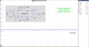
In posting #196, I mentioned that I came across a strange LF noise problem, that I initially thought to come from the used ZTX transistors.
After much soldering and exchanging components, it turned out that the transistors are perfectly o.k. and very consistent, but that the problem was caused by Nichicon Polymer electrolytic caps.
Replacing them by 6.3V 105 degrees Panasonic FM caps, the problem was completely gone.
See image below for the spectrum of the Voltage Amp taken from the SE output.
This as good as it can be.
After having to remove and replace the caps on the other 3 boards, I can finally start listening tests, hopefully in the coming week.
Hans
.
Attachments
- Status
- This old topic is closed. If you want to reopen this topic, contact a moderator using the "Report Post" button.
- Home
- Source & Line
- Analogue Source
- Designing a universal diff-in/diff-out Head Amp