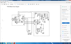
I am working on a buffer amplifier/ mid boost circuit. Here are the original schematics but are not accurate. My primary concern is the capacitors at C1. On my pcb, there is only 1 capacitor. The schematic shows 2, one of them in brackets.
My PCB also includes an F30A transistor
My PCB also includes an F30A transistor
Attachments
Last edited:
That diagram is *wrong*. Note that the battery + is connected directly to the 10K and the input signal. Can Not Work.
I have seen it recently but forget where. Search on (or post) the *name* of the thing and you can probably find a discussion on a guitar pedal forum.
EDIT - ah, this is one error swatted. There may be more?
I have seen it recently but forget where. Search on (or post) the *name* of the thing and you can probably find a discussion on a guitar pedal forum.
EDIT - ah, this is one error swatted. There may be more?
Attachments
Last edited:
- Status
- This old topic is closed. If you want to reopen this topic, contact a moderator using the "Report Post" button.