Hello everyone. I am building stages of DIY phono (or trying it) for some years.
I have read many articles about them, about RIAA, about power supplies, etc.
I have also built my first amplifiers and my first acoustic boxes.
But now I have come to have a modest audio system, consisting of acoustic boxes B & W dm602; Van den Hull cables; integrated amplifier Marantz PM6006; CD player Marantz CD 5400; direct turntable (1982) Aiwa AP2400 with AT440Mlb; Marantz ST6000 tuner.
Although the Marantz integrated amplifier has a phono stage, I am using the VSPS400 kit (for building the Emerald kit)
It's that its sound is more pleasant, less fatiguing.
I find that the phono stage of the Marantz, although it is good, has in my opinion an accentuation of treble that I estimate between 8 and 10 kHz which makes the music fatiguing.
I have not found the circuit of the phono stage of the Marantz PM6006, but I have seen that on the circuit board there are some inductors, one per channel at the phono input.
I found the circuit of the phono stage of the Marantz PM5004 and I see that these inductors are at the entrance of this stage. I also see cartridge loading capacitors. I think that if I remove them, using only the capacitance of the cable, it will improve that accentuation in treble
I would like someone to explain what function the inductors fulfill and what effect they have on the frequency response.
Greetings and thanks.
An externally hosted image should be here but it was not working when we last tested it.
+3 dB in 16khz. If I remove the capacitors and the load inductor, will I make a mess?
Are they put on purpose to highlight high frequencies ?.
I need someone from the forum to advise me.
Of all the stages of phono that I have built, none presents this configuration in the cartridge load.
But Marantz engineers would have done something about it.
I can not resist the temptation to remove them, charge with 47k, without a capacitor, using the capacitance of the cable (125p).
Greetings and advise me.

Nobody thinks?
I have been searching for this question for a long time.
I have read that in certain countries in Europe, the regulations regarding EMI, make the engineers or circuit designers include the inductors. Not so in other countries.
I have simulated in LTSpice without inductors and without load capacitors and the frequency response resembles all the circuits that I know, without that sharp accent that the graphics show.
I want someone to advise me, if I remove the inductor and the load capacitors of the phono stage of the Marantz PM6006 will make disaster ?.
The simulation in LTSpice would be reflected with reality ?.
Greetings.
Some MM cartridge manufacturers specify a load capacitance. The HF peak this gives compensates for mechanical HF rolloff in the cartridge. Therefore a simulation of the circuit along gives you only half the story.
The capacitance plus the inductor form an RF filter, which you may or may not need.
The capacitance plus the inductor form an RF filter, which you may or may not need.
Member
Joined 2009
Paid Member
Similar experience - I have an old Marantz integrated amplifier and I had to crank the treble control hard to the left to kill the fatigue on the phono when I last tried it out. I haven't tried to correct it as I don't use it much. I think it's worth playing with the input capacitance, at least that's where I'd likely start, just see if I could desolder one end of it and lift it clear to see how much impact it had. It might not be the right solution but I'd sure want to hear the impact to give me some idea as to how much influence it was on the sound and then use that information to decide next step - maybe try a capacitor of lesser value. I might also try reducing the load resistance to increase the damping of the cartridge resonance. Orignal circuit looks like two 100k in parallel for 50k, I might try reducing the total value to around 5k or 10k and listen for the impact again. Just tack another resistor in parallel to existing ones might be enough for that experiment. Oh, and I would do the change to only one channel at a time so I can compare original sound to modified sound by choosing which channel to listen.
Last edited:
Sorry, I meant to say "alone". Too late to edit it.DF96 said:Therefore a simulation of the circuit along gives you only half the story.
Some MM cartridge manufacturers specify a load capacitance. The HF peak this gives compensates for mechanical HF rolloff in the cartridge. Therefore a simulation of the circuit along gives you only half the story.
The capacitance plus the inductor form an RF filter, which you may or may not need.
There is of course no documented evidence of this mechanical roll off and MCs with exactly the same or higher moving mass seem immune to it.
The electrical model of an MM is MUCH more complex than most people use though. Hans and George have measured this.
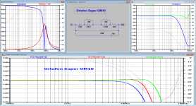
Glad you said ortofon as Hans measured one of those. Attached is his raw measurement, equivalent model and some loading examples. This is JUST the coil being measured and an end to end measurement still needs to be done. Now for this model (super OM) Ortofon give a bit of a barn door to aim at with 200pF-500pF recommended. Loading at 47k||150pF in the simulation as you can see gives an electrical roll off of 2dB at 15kHz so you can see that a higher capacitive load would be a way to reduce that. In fact a different resistive load does a far better job as can be seen.
This is by no means proof as there are missing measurements, but it's a pointer that this oft repeated statement about MMs having a mechanical roll-off might not actually be the case. Hopefully before too long we can get the missing measurements and make some progress.
This is by no means proof as there are missing measurements, but it's a pointer that this oft repeated statement about MMs having a mechanical roll-off might not actually be the case. Hopefully before too long we can get the missing measurements and make some progress.
Attachments
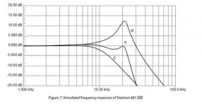
I've not seen measurements that isolate the different aspects, but would love to find some. There are some compelling analyses, for example the attached from a paper Steven Van Raalte did for linear audio (diagram attached with permission from Jan who is a good egg ") )
)
This shows the electrical roll off from the generator as 'E', the assumed mechanical resonance as 'M' and the combined output as 'S'. This fits some measurements I have seen so it would be easy to say case closed. Luckily there are still a few inquisitive types like Hans and George who will do measurements never published before.
All good harmless fun
)This shows the electrical roll off from the generator as 'E', the assumed mechanical resonance as 'M' and the combined output as 'S'. This fits some measurements I have seen so it would be easy to say case closed. Luckily there are still a few inquisitive types like Hans and George who will do measurements never published before.
All good harmless fun
Attachments
I've not seen measurements that isolate the different aspects, but would love to find some. There are some compelling analyses, for example the attached from a paper Steven Van Raalte did for linear audio (diagram attached with permission from Jan who is a good egg
This shows the electrical roll off from the generator as 'E', the assumed mechanical resonance as 'M' and the combined output as 'S'. This fits some measurements I have seen so it would be easy to say case closed. Luckily there are still a few inquisitive types like Hans and George who will do measurements never published before.
All good harmless fun
Hi,
Do you have links to Hans and Georges work?
Hi. Tinypic has removed all my schemes and simulations that I have published.
Reading the post published by Billshurv, I understand the mechanical compensation with the electric in the magnetic capsules on the high frequencies.
However, for example in AT 440 Mlb, a load of 47k and 100-200pF is specified.
These 100-200 pF are already in the interconnection cable.
Because Marantz adds 220pF + 220pF in the circuit.
I would add more than 600pF which for the AT440Mlb would be more than triple the capacitance.
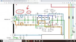
I also saw in the diagram that the inductor and resistor at the input, for certain models they have to be short-circuited, which indicates that these elements are to meet certain standards of some countries with respect to EMI. But they surely affect the sound result.
I don't know if I can publish the diagram again.
Regards.
Reading the post published by Billshurv, I understand the mechanical compensation with the electric in the magnetic capsules on the high frequencies.
However, for example in AT 440 Mlb, a load of 47k and 100-200pF is specified.
These 100-200 pF are already in the interconnection cable.
Because Marantz adds 220pF + 220pF in the circuit.
I would add more than 600pF which for the AT440Mlb would be more than triple the capacitance.
I also saw in the diagram that the inductor and resistor at the input, for certain models they have to be short-circuited, which indicates that these elements are to meet certain standards of some countries with respect to EMI. But they surely affect the sound result.
I don't know if I can publish the diagram again.
Regards.
Hi,
Do you have links to Hans and Georges work?
Yes. Start here Cartridge dynamic behaviour . You can get lost in the rest of the thread if you are not careful!
- Status
- This old topic is closed. If you want to reopen this topic, contact a moderator using the "Report Post" button.
- Home
- Source & Line
- Analogue Source
- Inductor in phono stage input