Hello
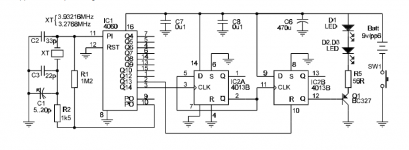
I'm tring to build a 100HZ strobe using this schematic from the internet.

I completed the work and as a rusult is a 100HZ light.
The problem is that the stobe marks are not crisp. They are too smoth as I could compare them with the other device. Here the photos.


Could somebody Help me to make the platter marks crisp?
I need 100HZ because the original glim lamp connected to power line (230volts 50Hz via a resistor) emitting light at both picks, means vibrating with 100Hz.
May be it's need to integrate 555 to the schematic?
I don't know what could I do to make it working=(
I tried different R4 and R5 with no effect and tried to remove C1 and C2. The light is the same! The strobe marks are visible but not crisp.
Thank you.
I'm tring to build a 100HZ strobe using this schematic from the internet.
I completed the work and as a rusult is a 100HZ light.
The problem is that the stobe marks are not crisp. They are too smoth as I could compare them with the other device. Here the photos.
Could somebody Help me to make the platter marks crisp?
I need 100HZ because the original glim lamp connected to power line (230volts 50Hz via a resistor) emitting light at both picks, means vibrating with 100Hz.
May be it's need to integrate 555 to the schematic?
I don't know what could I do to make it working=(
I tried different R4 and R5 with no effect and tried to remove C1 and C2. The light is the same! The strobe marks are visible but not crisp.
Thank you.
Last edited:

I also have found an strobe layout where 4013 pin 10 was conected to the 4060 Q13 but 4013 pin 4 was not. Do I need to connect both 4013 pins?
It depends on which output you use (50Hz or 100Hz). If you only use 100Hz, then you only need to connect pin 10.
I could any one? Q10 or Q12 or Q13?
The lower you go, the shorter the duty cycle. On extremely short duty cycles, you may need to lower R4 to increase perceived brightness.
Hello,
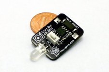
I built this long ago >6 years? based on this free design at Vinyl Engine.
DIY Strobe - Turntable Timing Light - Vinyl Engine
I improved it by using 3 bright white LED in a row thats bright enough.
Vary R5 to suit whatever brightness level you seek.
Its a very very useful tool, full appreciation and credit to the designer who shared this project for all.
I've no skill in pcb design, can anyone like to share a compact PCB on Oshpark? I hope to buy some as I think I need to replace mine which is crap and I'm wanting a better pcb for this.
Attachments
Last edited:
There is a strobe available here for $13: Turntable Strobe from Bot Thoughts Llc on Tindie
I don't think you could build one for that price.....
I don't think you could build one for that price.....
Attachments
I've no skill in pcb design, can anyone like to share a compact PCB on Oshpark? I hope to buy some as I think I need to replace mine which is crap and I'm wanting a better pcb for this.
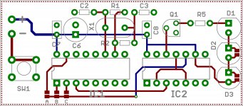
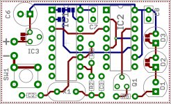
Something like this?
The PCB is 1.1" x 2.5". I didn't include variable cap C1, as it will have only a microscopic effect on the final frequency (±300Hz/32768). I plotted pads for 3 LEDs. If only one (or two) are used, the solder jumpers for the unused positions should be bridged; the value of R5 will need to be adjusted accordingly.
Feedback for the duty cycle can be taken from Q10/Q12/Q13 by installing solder jumper A/B/C (only one jumper).
Attachments
That is the easiest solution and is very accurate if the code is rightAn Arduino Nano & LED combo would allow you to program the pulse as narrow as you liked.
Something like this?
Wow!.Good job and I appreciate it. Could the 2 Ic's be somehow be placed vertical side by side to be more compact?
I tried to connect pins 10 & 4 to one of the lower outputs of the 4060 (Q10-Q13).. I tried all Q10, Q12 and Q13. The result is that the strobe markes dissapeared. I see just the diffecent light from the led.
I wanted to use this strobe becouse it allows to use 18v that is going from my turntable.
Other variants are working only 6V or 14v max.
Could we improve the initial strobe? Is it possible?
I wanted to use this strobe becouse it allows to use 18v that is going from my turntable.
Other variants are working only 6V or 14v max.
Could we improve the initial strobe? Is it possible?
I also made it a couple of years ago(based on v engine site). I solved the power problem with the v regulator on the same pcb..you can use even to92 size regulator due small current.grounding should be done in correct way...you can induce 100hz from strobo to pickup chain...
Something like this?
The PCB is 1.1" x 2.5". I didn't include variable cap C1, as it will have only a microscopic effect on the final frequency (±300Hz/32768). I plotted pads for 3 LEDs. If only one (or two) are used, the solder jumpers for the unused positions should be bridged; the value of R5 will need to be adjusted accordingly.
Feedback for the duty cycle can be taken from Q10/Q12/Q13 by installing solder jumper A/B/C (only one jumper).
Could you help to integrate in your pcb layout voltage regulator so this device could work from 18VDC?
My 4060B and 4013B could work from up to 18V. Do I need to do more to adobe your pcb to work with 18V?
There is a strobe available here for $13: Turntable Strobe from Bot Thoughts Llc on Tindie
I don't think you could build one for that price.....
Most probably you're right in terms of costs. But the pic shows a 60 Hz strobo, while you may need a 120 Hz one, and we in our part of the world a 100 Hz one.
Best regards!
- Status
- This old topic is closed. If you want to reopen this topic, contact a moderator using the "Report Post" button.
- Home
- Source & Line
- Analogue Source
- Help me please with this turntable 100Hz strobe