I just googled "AT89C2051 Programmer" and came up with this:
Atmel AT89C2051
Scroll down to "Device Programmers" and there is a list of mfrs.
There also appeared to be a number of DIY hobby level projects for building your own.
Not all of these programmers are LPT based. I have a Phillips LPC (small pin count 8051 device) series programmer which is USB and works in W7.
2 decades ago I had some brief experience with some local produced (from Asia) Eprom programmers and was quite an expensive piece of equipment targeted at industry end users. IIRC, it comms with the PC through the serial com port, with its own DOS based program. I used it to revive corrupted or wrongly flashed PC bios flash roms. It worked nicely. and saved the day.
I was looking at Aliexpress China, came across quite a number of Model TL866 universal programmer, priced accordingly to number of bundled socket adapters for wide range compatibility. Some sellers provide or link to chip compatibility list and 8051 chips seemed compatible. I was thinking of acquiring one for educational purpose and to learn something new. Its USB interface.
My other alternative (after asking around) is to have the uP programmed by some 3rd party vendor who offer such services for a tiny fee and be done with that.
Hi all,
Anyone here built the 89C2051 based strobe light recently?
I've already built mine and also bought an affordable Atmel programmer to flash the MCU.
After that I fixed 1 led to see if it works. What I noticed was it flashed brightly for half a second, then dimmed down to acceptable brightness at 50hz. (mine is 50hz version). Is that correct?
There's one part I didn't use as specified in the DS1833 supervisor reset IC. I had selected another IC with similar specs. MCP101-475HI/TO, only difference is the pinout are reversed. just swap the other way round and its correct. I'm not sure if the new IC is contributing to this unusual issue. I had thought it would work correctly, it all light up at 50hz spot on. No problem with that.
The other 4013/4060 based pcb project all works a charm, no issues.
Attachments
What programmer did you use?
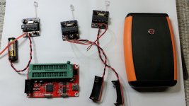
This: MCU SCM 24/93 Series EEPROM Programmer Burner SP200SE/SP200S with ISP Interface 665950128473 | eBay
Software and drivers here: SP200SE- Device Programmer - 8051/52, AVR, EEPROM Programmer
Note that Pin 1 at the ZIF socket is diagonally across the lever. Its manufactured this way.
The programmer is seen in the picture above at the bottom.
Last edited:
The LED will be on for the reset time and will appear brighter as it is 100% duty cycle instead of 6% when running at 100Hz.
You can shorten the reset time by replacing U2 with a 0.47uFd tantalum cap, plus side to 5V and minus side to uP pin 1. You could probably go as low as 0.1uFd.
You can shorten the reset time by replacing U2 with a 0.47uFd tantalum cap, plus side to 5V and minus side to uP pin 1. You could probably go as low as 0.1uFd.
Hello,
I built this long ago >6 years? based on this free design at Vinyl Engine.
DIY Strobe - Turntable Timing Light - Vinyl Engine
I improved it by using 3 bright white LED in a row thats bright enough.
Vary R5 to suit whatever brightness level you seek.
Its a very very useful tool, full appreciation and credit to the designer who shared this project for all.
I've no skill in pcb design, can anyone like to share a compact PCB on Oshpark? I hope to buy some as I think I need to replace mine which is crap and I'm wanting a better pcb for this.
This works. The second flip-flop D-type limited the duty-cycle by the clock of the reset.
I did it.
Cheers
Could somebody help me to understand the value of the current limiting resistor r5?
I have it 56Ohm for the one yello led. Normal current of the led is 20ma. Forward Voltage is 2.1V. (Forward Current 25ma. Reverse Voltage 5V).
I check the voltage with my DWM on the led and it's only 0,55V. Why it's so? Should it be 2.1 to get the maximum light intensity?
I have it 56Ohm for the one yello led. Normal current of the led is 20ma. Forward Voltage is 2.1V. (Forward Current 25ma. Reverse Voltage 5V).
I check the voltage with my DWM on the led and it's only 0,55V. Why it's so? Should it be 2.1 to get the maximum light intensity?
There are several plans in this thread. Which one are you using?
You do not have to run an LED "on spec". 20mA-30mA is a MAXimum, not a requirement. You can run a lower current if it is bright enough. (It will live longer; not that we care for this job.)
"Formula" is just Ohm's Law.
You do not have to run an LED "on spec". 20mA-30mA is a MAXimum, not a requirement. You can run a lower current if it is bright enough. (It will live longer; not that we care for this job.)
"Formula" is just Ohm's Law.
I think I've sorted it out. Remove the reset IC, solder 22nf capacitor to +5 and reset pin.
Tried with various values on hand. 22nf seems to suit. I also replaced R2 with 12ohm for 3 generic super bright white LED.
I have the same behaviour. Could I use a simple 22nf capacitor (not a tantalum)?
I have the same behaviour. Could I use a simple 22nf capacitor (not a tantalum)?
I reckon any tiny poly 22nf film will work.
- Status
- This old topic is closed. If you want to reopen this topic, contact a moderator using the "Report Post" button.
- Home
- Source & Line
- Analogue Source
- Help me please with this turntable 100Hz strobe