In other words if you drive the circuit with a voltage in series with R you get a large voltage gain, but obviously no power gain.
LD I hope you're with me here, it's an impedance transformation so the voltage goes up and the current goes down (or visa-versa) just like with a transformer so the power/energy is constant. The relationship between R and Q squared in the L/C circuit is analogous to R and N squared in a transformer.
I finalized my search for finding replacements circuits for all 5 Carts that Bill made available.
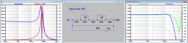
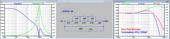
There are great differences, like between the inductance of the Ortofon 40 versus the Denon DL-107.
Nevertheless most carts seem to perform quite well in a classical voltage amp setup.
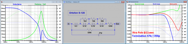
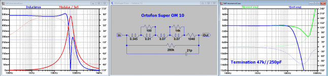
All Ortofons needed a somewhat larger cap of resp. 250pF for the Ortofon Super OM10 and the Ortofon 40, and 350pF for the Ortofon S-120 to prevent an early roll off at high end
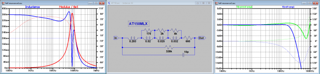
The Denon DL-107 and the AT 150MLX where fine with 47k//150pF.
For the Virtual ground topology, the Ortofon 40 and S-120 did not respond that well, despite meticulous tuning to cancel the created pole and needed an extra 11usec pole to keep HF under control.
The other 3 Carts didn’t need such correction.
All 5 Carts showed an extended BW in the Virtual Ground topology, just as expected.
My test gear was suited for testing above 2mV on the Cart. To go any lower will need the use of bandpass filters to lower the scopes noise of 100uV.
Although these filters are available, it will make the testing process to take considerable more time and for the moment I don’t see a real need to go much lower.
One thing has to be kept in mind. I measured the replacement circuits as if a constant voltage is generated by the motor when playing at CV.
This will most likely not be the case, so when knowing the recorded FR from a well known test record, like the CH Precision record up to 30kHz or the Ortofon record up to 50kHz, both played at 45rpm,will enable to finding the transfer function from CV to motor voltage.
This would definitely help to get more insight in the Carts functioning.
I leave this recording job for these 5 Carts to someone else since my system is not optimised for MM Carts, but will be happy to help in finding the missing transfer function.
To keep things together, the final results for all 5 Carts together are attached.
Hans
There are great differences, like between the inductance of the Ortofon 40 versus the Denon DL-107.
Nevertheless most carts seem to perform quite well in a classical voltage amp setup.
All Ortofons needed a somewhat larger cap of resp. 250pF for the Ortofon Super OM10 and the Ortofon 40, and 350pF for the Ortofon S-120 to prevent an early roll off at high end
The Denon DL-107 and the AT 150MLX where fine with 47k//150pF.
For the Virtual ground topology, the Ortofon 40 and S-120 did not respond that well, despite meticulous tuning to cancel the created pole and needed an extra 11usec pole to keep HF under control.
The other 3 Carts didn’t need such correction.
All 5 Carts showed an extended BW in the Virtual Ground topology, just as expected.
My test gear was suited for testing above 2mV on the Cart. To go any lower will need the use of bandpass filters to lower the scopes noise of 100uV.
Although these filters are available, it will make the testing process to take considerable more time and for the moment I don’t see a real need to go much lower.
One thing has to be kept in mind. I measured the replacement circuits as if a constant voltage is generated by the motor when playing at CV.
This will most likely not be the case, so when knowing the recorded FR from a well known test record, like the CH Precision record up to 30kHz or the Ortofon record up to 50kHz, both played at 45rpm,will enable to finding the transfer function from CV to motor voltage.
This would definitely help to get more insight in the Carts functioning.
I leave this recording job for these 5 Carts to someone else since my system is not optimised for MM Carts, but will be happy to help in finding the missing transfer function.
To keep things together, the final results for all 5 Carts together are attached.
Hans
Attachments
Hans, that's really interesting, particularly as it shows a real difference between the solid and split pin ortofon generators. The DL-107 is a very pleasant suprise as shows that their patented design does work as described and that they knew their onions before I was born!
I'll get something set up to measure FR ASAP.
My oddball lo-Z MMs are still in transit from Russia. When they arrive they are having a detour to Belgium for a friend to try them. If you have the time to run those as well let me know.
I'll get something set up to measure FR ASAP.
My oddball lo-Z MMs are still in transit from Russia. When they arrive they are having a detour to Belgium for a friend to try them. If you have the time to run those as well let me know.
Yes, thank you Scott - I get it now. Noise power remains unaltered: it is as you say a source impedance transformation.LD I hope you're with me here, it's an impedance transformation so the voltage goes up and the current goes down (or visa-versa) just like with a transformer so the power/energy is constant. The relationship between R and Q squared in the L/C circuit is analogous to R and N squared in a transformer.
Then noise voltage would follow Re versus f, and not be white.
A way to validate the cart's impedance at very low signal levels would be to observe voltage noise spectrum - not easy though?
LD
Yes, thank you Scott - I get it now. Noise power remains unaltered: it is as you say a source impedance transformation.
Then noise voltage would follow Re versus f, and not be white.
A way to validate the cart's impedance at very low signal levels would be to observe voltage noise spectrum - not easy though?
LD
Are you still interested in very low signal levels ?
Then please select one of the 5 Cart’s that I tested and I will process that guy.
Noise BW now is 100MHz, so I can go a factor 100 down in noise when restricting to 10kHz.
Now that I have the wideband data I only have to compare.
Hans
Last edited:
LD,
I took one sample with the Ortofon Super OM 10, the one that was rapidly increasing its inductance at voltages above 30mV.
Now just as a simple test at 1kHz, with restricted noise BW, where in the bode diagram with the 4k7 series resistor gain was -6.0dB with a phase of 42.5 degrees, I went from 11.4mV to 24.4uv on the cart, a full 53 dB down with no measurable change in gain and phase. Since these gain and phase figures are 1:1 related to the inductance, this tells that Inductance doesn't change over this range.
Let me just know if you want me to do any other test now that I still have everything set up and working properly.
Hans
A way to validate the cart's impedance at very low signal levels would be to observe voltage noise spectrum - not easy though?
LD
I did plot 25yr. ago to show why you don't want to use a super low noise bi-polar with a MM cart. I just used a fixed gain of 200 pre-amp in front of an HP dynamic signal analyzer and the noise was easy to resolve. IIRC it was an AT cart with an 800 OHM DC resistance. The difference between the AD745 and LT1028 was large, but with the 5534 not as much but the FET still won.
I even could go a bit lower to 10.7uV on the OM 10 Cart, 60 dB below 11.4mV that was mentioned before as an upper limit.
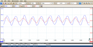
See screen capture below, not the nicest possible waveforms, bit still 6dB apart.
Channel A is the reference input with 21.2uV and channel B with 10.7uV the node between Cart and 4k7.
Measured RMS voltages are displayed in the bottom line.
I used the scope's internal 50* amp, so noise is still there, but now with BW limited to 3kHz.
Hans
Attachments
Thx Hans - I think this confirms Davidsrsb's result on a Goldring MM cart that showed no inductance or loss variation.I took one sample with the Ortofon Super OM 10, the one that was rapidly increasing its inductance at voltages above 30mV.
Now just as a simple test at 1kHz, with restricted noise BW, where in the bode diagram with the 4k7 series resistor gain was -6.0dB with a phase of 42.5 degrees, I went from 11.4mV to 24.4uv on the cart, a full 53 dB down with no measurable change in gain and phase. Since these gain and phase figures are 1:1 related to the inductance, this tells that Inductance doesn't change over this range.
I am surprised and perplexed, but happy to accept it.
I wonder why the same OM10 shows variation at higher stimulus levels? Is the stylus assembly fitted or is this just the body?
LD
OM10 is with the stylus assembly fitted.Thx Hans - I think this confirms Davidsrsb's result on a Goldring MM cart that showed no inductance or loss variation.
I am surprised and perplexed, but happy to accept it.
I wonder why the same OM10 shows variation at higher stimulus levels? Is the stylus assembly fitted or is this just the body?
LD
Hans
Well, I think that when all useful and relevant info's from these Carts are extracted satisfactory, testing ends here, unless someone still has some wish that I can possibly realise.
It was a nice job, learning a lot about different Carts, and showed the almost impossibility to create an accurate replacement circuit when the par. cap is not known.
It was also quite obvious that a split coil model is too simple and that the coil has to be split into 3 or 4 parts to make it possible to exactly follow the inductance curve.
I'm looking forward to see the recorded FR response from these Carts, preferably from a CV record, to find the still missing piece, being the motor transfer function (MTF).
For the sake of this test, this MTF was taken as a proportional to CV and frequency independent relation.
Hans
I think it worth exploring why inductance changes significantly with level for the OM10 at higher than normal signal levels. If it's easy, a quick repeat of that test without the stylus assembly fitted might be interesting?
LD
No Problem, is it also O.K. for you Bill that I remove the stylus temporarily ?
Hans
LD,
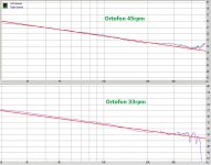
I varied the voltage over the Cart, that is to say, the cart with 4700Ohm in series.
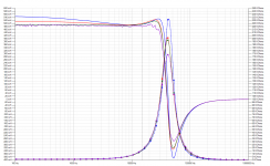
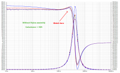
Looking at 100Hz in the images below, I went from top to bottom in 4 steps from 450mV,135mV, 4.5mV to 0.45mV.
450mV looks like a lot, but with the series resistor the current through the Cart will still be below 80uA.
There is only one difference between the two images resp. with and without stylus assembly, and that is for the 0.45mV curve between 15kHz and 30kHz where the stylus assembly causes a drop in inductance, whereas without stylus assembly the 0.45mV curve neatly follows the 4.5mV curve.
This is very repeatable and not in any way caused by noise.
Hope it brings you any further in your thoughts.
Hans
I varied the voltage over the Cart, that is to say, the cart with 4700Ohm in series.
Looking at 100Hz in the images below, I went from top to bottom in 4 steps from 450mV,135mV, 4.5mV to 0.45mV.
450mV looks like a lot, but with the series resistor the current through the Cart will still be below 80uA.
There is only one difference between the two images resp. with and without stylus assembly, and that is for the 0.45mV curve between 15kHz and 30kHz where the stylus assembly causes a drop in inductance, whereas without stylus assembly the 0.45mV curve neatly follows the 4.5mV curve.
This is very repeatable and not in any way caused by noise.
Hope it brings you any further in your thoughts.
Hans
Attachments
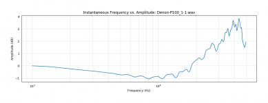
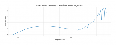
It was already determined the Ortofon test record was crap, right?
Which tracks, I recall some serious issues with pink noise on the LP's cut in the 50's - 70's, but that difference looks bad???? The Denon has a warp?
BTW thanks to JP for prettying up the plots, there is also a better smoothing algorithm now.
Last edited:
I don't agree that it is crap.It was already determined the Ortofon test record was crap, right?
The Square wave might be a mysterious signal, but the CV sweep is useful up to 50kHz when playing the record at 45rpm.
I post the result again.
Hans
Attachments
can you attach the file?
Your Ortofon recording shows the same two dips before and after 40 kHz as mine.
That confirms that it is not just my record having an anomaly.
What I don’t understand is why your FR goes up by 8dB from the straight at high end where in my case it deviates less than 3dB. Could that have anything to do with the still experimental extraction program that you are using ?
I’ll make the 45rpm .wav file available tomorrow and it would be nice when you could also make available an Ortofon recording at 45rpm to compare results.
Hans
- Status
- This old topic is closed. If you want to reopen this topic, contact a moderator using the "Report Post" button.
- Home
- Source & Line
- Analogue Source
- Cartridge dynamic behaviour