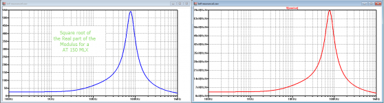
When taking the sqrt of the Re part of the modulus of the AT150 MLX (noise goes with the sqrt of R) and plotting the noise that LTSpice calculates for this very Cart, both curves are exactly the same in shape.Put another way, if the noise is not white where does the extra energy come from?
LD
The calculated noise here obviously follows the thermal noise math.
Hans
Attachments
Does the spectrum of Johnson noise follow the Re versus f curve?
LD
Not sure what you are asking. In a resonant system the Q is directly related to the total loss per cycle. If you model the system as an ideal L and C and replace all loss as a resistance you get the Johnson noise of that resistance driving the system with the frequency shape of the resonant system. I can't find Nyquist's original paper right now with a fairly brilliant one page derivation of 4KTR. SPICE only knows R/L/C so it will always give this answer, and I have measured it. Also we are talking self noise at equilibrium i.e. nV and pA and none of the drive level dependent effects are relevant.
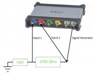
After having played with several set-ups, I finally chose for the most simple one.
I have a programmable USB scope, a Picotec 5243B, with built in function generator.
With an input impedance of 14pF//1Meg, a frequency range up to 100Mhz resulting in 100uV input noise (or 10nVRtHz), applying 5mV to the Cart means a S/N ratio of 34dB.
Originally my plan was to insert an amp in between with a lower noise contribution, but results are good enough to calculate the replacement cicuits.
See first image below.
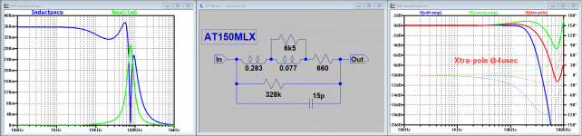
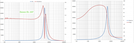
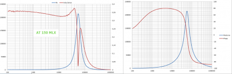
From the measured bode diagrams, I extracted the Cart's modulus and phase. From modulus and phase, I calculated the Imaginary and the Real value and the inductance.
Measured results from the 5 Carts that Bill made available are in the second to sixth image.
Next step is to get the Cart's replacement circuit using LTSpice, still with the scope's 14pF//1Meg in place till perfectly matching the measured results.
Once found, I remove the 14pF//1Meg from the sim to finally get the exact inductance and transfer curves.
See the seventh image, in this case for the final AT 150 MLX, the other 4 Carts soon to follow.
Hans
I have a programmable USB scope, a Picotec 5243B, with built in function generator.
With an input impedance of 14pF//1Meg, a frequency range up to 100Mhz resulting in 100uV input noise (or 10nVRtHz), applying 5mV to the Cart means a S/N ratio of 34dB.
Originally my plan was to insert an amp in between with a lower noise contribution, but results are good enough to calculate the replacement cicuits.
See first image below.
From the measured bode diagrams, I extracted the Cart's modulus and phase. From modulus and phase, I calculated the Imaginary and the Real value and the inductance.
Measured results from the 5 Carts that Bill made available are in the second to sixth image.
Next step is to get the Cart's replacement circuit using LTSpice, still with the scope's 14pF//1Meg in place till perfectly matching the measured results.
Once found, I remove the 14pF//1Meg from the sim to finally get the exact inductance and transfer curves.
See the seventh image, in this case for the final AT 150 MLX, the other 4 Carts soon to follow.
Hans
Attachments
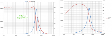
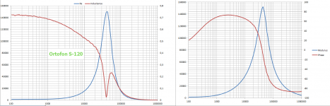
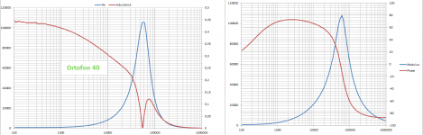
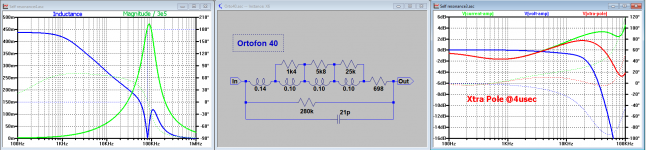
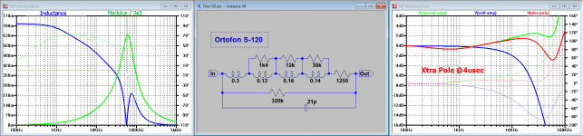
Now the results for the Ortofon 40 and the Ortofon S-120.
Quite obvious, while trying to find the replacement circuit, was that a single split coil model is too simple.
In this case I have split the coil in 4 pieces to give satisfiable results.
The effect on the FR becomes quite clear, for both types of preamps.
Tomorrow I will redo the AT150MLX, now with more coil splits, letting the inductance roll off to start a bit earlier.
Hans
Attachments
I would note that the S-120 was never intended by Ortofon to give output much above 18kHz. I have it (LD fault) as a potential mono cartridge and also for it's tracking ability, at least at LF where it is superb. With a chunky DJ high output winding I would expect it to be the least tameable. I may end up pleasantly suprised!
After having played with several set-ups, I finally chose for the most simple one.
I have a programmable USB scope, a Picotec 5243B, with built in function generator.
With an input impedance of 14pF//1Meg, a frequency range up to 100Mhz resulting in 100uV input noise (or 10nVRtHz), applying 5mV to the Cart means a S/N ratio of 34dB.
Originally my plan was to insert an amp in between with a lower noise contribution, but results are good enough to calculate the replacement cicuits.
Hans
You may be able to improve the SNR with an attenuation network on the output so you can run the Picoscope at near full level. Possibly a 50 Ohm resistor in series with a 5 Ohm resistor (or .5 Ohm for around 40 dB of attenuation. Then the noise in the source (its not that great) will be reduced with the signal. you could also use a stereo head amp to boost the measured signals going back to the Picoscope. If its nonflat the difference will still be accurate as long as the channels track.
I can’t understand what is the physics behind Re peaking at L-C resonance.
I was under the impression that Re represents the sum of the ohmic and the dissipative phenomena (eddy current and hysteresis losses).
As far as I know, ohmic should be flat with freq, eddy current and hysteresis losses increasing with freq.
What makes Re drop past F resonance?
George
I was under the impression that Re represents the sum of the ohmic and the dissipative phenomena (eddy current and hysteresis losses).
As far as I know, ohmic should be flat with freq, eddy current and hysteresis losses increasing with freq.
What makes Re drop past F resonance?
George
Thanks for your suggestions.You may be able to improve the SNR with an attenuation network on the output so you can run the Picoscope at near full level. Possibly a 50 Ohm resistor in series with a 5 Ohm resistor (or .5 Ohm for around 40 dB of attenuation. Then the noise in the source (its not that great) will be reduced with the signal. you could also use a stereo head amp to boost the measured signals going back to the Picoscope. If its nonflat the difference will still be accurate as long as the channels track.
The signal in the Picoscope is digitally generated.
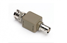
For low levels it only has a few steps with awful quantisation noise.
For that reason I have a -20db and a -40dB attenuator to insert in the line, see image below. But then there is still the 100uV noise from the input itself.
I turned out that -20dB attenuation from the signal generator was enough when using 300mV pk-pk @ -70dB noise, more attenuation did not bring an advantage.
This gives ca. 10mV eff on the Cart with ca. 40dB S/N. With the 4k7 resistor in series, current through the Cart is still a very low 2uA max.
Hans
Attachments
George,I can’t understand what is the physics behind Re peaking at L-C resonance.
I was under the impression that Re represents the sum of the ohmic and the dissipative phenomena (eddy current and hysteresis losses).
As far as I know, ohmic should be flat with freq, eddy current and hysteresis losses increasing with freq.
What makes Re drop past F resonance?
George
At L-C resonance, phase is 0 degrees and impedance theoretically infinite.
L and C cancel each other so to say.
When measuring (the modulus of) the impedance at Fres you will see the par. resistance consisting of mainly the large resistor in the Cart's replacement circuit.
At frequencies below 100Hz you can measure the ESR of the Cart's coil.
When splitting the modulus in Re and Im, you will be able to find the value of the serie cap when looking at frequencies from 100Khz and above and also its ESR at frequencies from 1Mhz and above.
That's why it is important to measure with a large BW because you need to know the value of the par. cap.
Knowing Fres and the value of this cap, you can guessimate which part of the coil is not shunted by resistors.
Hans
The definition of Re arises due to cancellation of current phase-lag and phase-lead in self-inductance and self-capacitance of the coil. The outcome is that the impedance is deemed 'real' because it has in-phase current and voltage.I can’t understand what is the physics behind Re peaking at L-C resonance.
I was under the impression that Re represents the sum of the ohmic and the dissipative phenomena (eddy current and hysteresis losses).
As far as I know, ohmic should be flat with freq, eddy current and hysteresis losses increasing with freq.
What makes Re drop past F resonance?
George
In practice, the LCR system has a well-known phase response that means, by our definition of Re, the impedance at resonance is purely 'resistive', and has shoulders that are partly resistive. And large in value.
I totally empathise with you George as to the lack of this as a satisfying explanation of involved physics. This is why I challenge that Re can be 'real' in the classic sense that it can convert energy and generate noise. Neither the inductor nor the capacitor element can do that, only the coil resistance.
Other loss mechanisms, such as eddy loss and hyst loss are loosely linked to frequency because of repetition, and uninvolved in resonant behaviour. More linked to level, not minimum phase and not linear.
Not very satisfying, IMHO.
LD
Just because they cancel each other, their theoretical impedance at Fres is infinite, so regarding it as a resistor would mean a noise contribution proportional to sqrt(infinite), which is happily not the case.This is why I challenge that Re can be 'real' in the classic sense that it can convert energy and generate noise. Neither the inductor nor the capacitor element can do that, only the coil resistance.
Not very satisfying, IMHO.
LD
Although phase being zero and thus impedance being real, their generated noise is still the sum of both of their noises and because both being zero, it's a noiseless resistor in my view.
And as you say, only their ESR can generate and dissipate but not the L-C combo.
Hans
Last edited:
<snip> I can't find Nyquist's original paper right now with a fairly brilliant one page derivation of 4KTR. SPICE only knows R/L/C so it will always give this answer, and I have measured it. Also we are talking self noise at equilibrium i.e. nV and pA and none of the drive level dependent effects are relevant.
This one is a bit longer,but ... :
Nyquist, H.; Thermal Agitation of Electric Charge in Conductors*; Physical Review, Volume 32, July 1928, 110
http://123.physics.ucdavis.edu/johnson_files/nyquist_1928.pdf
This one is a bit longer,but ... :
Nyquist, H.; Thermal Agitation of Electric Charge in Conductors*; Physical Review, Volume 32, July 1928, 110
http://123.physics.ucdavis.edu/johnson_files/nyquist_1928.pdf
That is probably it and I just pictured the first couple of figures in my head, figure two and the basic appeal to the second law were what I was referring to.
Other loss mechanisms, such as eddy loss and hyst loss are loosely linked to frequency because of repetition, and uninvolved in resonant behaviour. More linked to level, not minimum phase and not linear.
Not very satisfying, IMHO.
LD
But as I pointed out before you are making a model via a stimulus, you are not making one based solely on a measurement of the noise in such a way that the system is not disturbed. Once you make a model of the behavior at a particular drive level in SPICE it will always give you the noise of the resistors you have inserted.
OK - so without a stimulus the only noise source is the coil resistance. Then the integral of energy over a given bandwidth can't be greater than originates from that resistance. So is the noise white, or does it follow the Re versus f curve? I think noise is obliged to follow the Re versus f curve. Just don't understand where the extra energy comes from...…………..But as I pointed out before you are making a model via a stimulus, you are not making one based solely on a measurement of the noise in such a way that the system is not disturbed.
I'm not thinking spice equivalents - just thinking of the cartridge coil impedance as a one port network, and not caring what's inside. There's no doubt that driven at resonance, the (large) impedance appears to be real and resistive.Once you make a model of the behavior at a particular drive level in SPICE it will always give you the noise of the resistors you have inserted.
LD
Just stumbled across a whole different issue.
When working on the Super OM10, I didn't understand the large difference in Inductance that George recently measured of 580mH versus my measurements of slightly under 500mH
That's why I experimented measuring with different voltages, and indeed above 10mV on the cart, Inductance ramps up quite rapidly and even more noticeable, inductance versus frequency gets a different shape.
In the other direction from 10mv I can go to 2mV, a factor 5, with no measurable changes.
The other Carts have more stable properties.
Just wanted to let you know.
Hans
Just don't understand where the extra energy comes from...…………..
LD
There is no extra energy, take say a .35H L with 1k series R and a 250pf capacitor. This resonates at about 17K with a peak noise of 150nV due solely to the 4nV white noise of the 1K R. You need to think of old fashion series parallel impedance transformations. At resonance the parallel impedance looks like a real 1.4M and we can't tell the difference.
In other words if you drive the circuit with a voltage in series with R you get a large voltage gain, but obviously no power gain.
Bill,Hans, very interesting as the superOM is rated at 4mV for 5cm/s output, so 10mV is not impossible. The S120 is rated at 10mV for the same stimulus
10mV is still fine, I'm talking of voltages 5 times as much or even more where inductance is ramping up rapidly.
Hans
- Status
- This old topic is closed. If you want to reopen this topic, contact a moderator using the "Report Post" button.
- Home
- Source & Line
- Analogue Source
- Cartridge dynamic behaviour