Bill, which of the oh so many designs are referring to, Aurak, SE, Balanced in/out, Head Amp plus digital, full analog, SMD, etc, etc ?More seriously I wonder if we are not at the point where the design is proven enough that it's time to lay out a board and release the gerbers to anyone who wants a try. I believe everyone who contributed is happy with the open HW concept around it? Does of course depend if LD decides the negative R path is better.

I will try out the negative R version, but I'm thinking it's prob not one for the fainthearts...…….it will need good protection to avoid consequences of accidentally running without a cart fitted, or a dodgy cart connection path...……Does of course depend if LD decides the negative R path is better
Yes the SE Aurak is by far the most straightforward. One note is that GBW of the first stage opamp matters - at least 13MHz IIRC, and so needs the usual care with layout and hf comp to see it stable. But nothing exotic or to worry about. I didn't do a PCB, mine is on vero so it can't be that tricky.
I also did a pentode version using EF184s which is cute if a tad noisy when not playing back, of course.
LD
Here are the Gerber files for SE Aurak
https://www.diyaudio.com/forums/att...90780219-mechanical-resonance-mms-drawing-jpg
https://www.diyaudio.com/forums/att...1161267-mechanical-resonance-mms-dscn3759-jpg
George
https://www.diyaudio.com/forums/att...90780219-mechanical-resonance-mms-drawing-jpg
https://www.diyaudio.com/forums/att...1161267-mechanical-resonance-mms-dscn3759-jpg
George
Donate? Scott normally donates 8-legs to us
Does of course depend if LD decides the negative R path is better
I just realized LD used my 745's.
I have a stash of the original 8-leg version, no idea why there is only a 16 pin SMT still in production.Yes the STR-112 has "square" waves and 500-50k constant velocity sweeps all without RIAA. Under a microscope the square waves visually are perfect triangles. The note that comes with it quite carefully lists the groove dimensions, etc.
Last edited:
There is an STR-112 on the auction site at the moment at not silly money. Might put a punt on that.
I picked up a used AT-33 PTG a few months back that needs a new diamond. Looking at the FR plot that came with that, which goes all the way to 20kHz unlike most there is a 2dB shelf at 10kHz but you can see it starting to rise just before cutoff. I'll try and scan that on monday.
I picked up a used AT-33 PTG a few months back that needs a new diamond. Looking at the FR plot that came with that, which goes all the way to 20kHz unlike most there is a 2dB shelf at 10kHz but you can see it starting to rise just before cutoff. I'll try and scan that on monday.
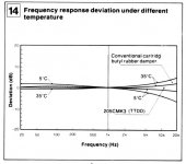
It's a good thought. Polymers and elastomers one might predict would show parametric changes over a few 10s of deg C, whereas metals such as cantilvers wouldn't.If I could repeat the frequency sweeps in the garage with all the equipment stabilized at 40F or so would that help separate mechanical from electrical effects? My personal experience is that anything that depends on the properties of rubber or elastomers changes with temperature more dramatically than any electrical parameters.
If the resonance were spring-mass involving vinyl polymer one might expect variation, whereas if cantilever beam resonance not.
LD
Yes the SE Aurak is by far the most straightforward. One note is that GBW of the first stage opamp matters - at least 13MHz IIRC, and so needs the usual care with layout and hf comp to see it stable. But nothing exotic or to worry about. I didn't do a PCB, mine is on vero so it can't be that tricky.
LD
LD,
You probably mean the GBW of the second amp. The first one has its 0dB gain crossing already at 20kHz, but the second Amp goes on from there with 25dB gain until 700Khz when using a GBW of 13MHz.
A bit less GBW wouldn't hurt, but this second amp should definitely be faster as the first one.
Raising the gain of the first stage a bit, giving also a benefit in noise contribution and lowering the gain of the second stage accordingly would result in a more balanced GBW distribution between both amps IMO.
Hans
That's quite an interesting graph, you always know where to find your stuff !Attached graph from the Technics EPC205C Mk3 user manual
Here are the Gerber files for SE Aurak
https://www.diyaudio.com/forums/att...90780219-mechanical-resonance-mms-drawing-jpg
https://www.diyaudio.com/forums/att...1161267-mechanical-resonance-mms-dscn3759-jpg
George
I don't think that all of the R and C values are correct.
I don't think that all of the R and C values are correct.
4k7 should be 10k
Thanks.
LD suggested those values when I asked him an adaptation for the Shure M97xE. I had shown measurements and Hans had simulated it.
mechanical resonance in MMs
mechanical resonance in MMs
mechanical resonance in MMs
George
LD suggested those values when I asked him an adaptation for the Shure M97xE. I had shown measurements and Hans had simulated it.
mechanical resonance in MMs
mechanical resonance in MMs
mechanical resonance in MMs
George
Attachments
George,Thanks.
LD suggested those values when I asked him an adaptation for the Shure M97xE. I had shown measurements and Hans had simulated it.
mechanical resonance in MMs
mechanical resonance in MMs
mechanical resonance in MMs
George
This may have been a version where you needed a different math than R=2*Lc-Rc, could that be the case ?
In that case everthing gets different.
Hans
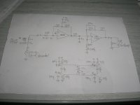
I worked out an idea for a universal Aurak, maybe this could be used for making a PCB.
This version can be used in combination with a sound processor, in that case also receiving it's power through the phantom XLR connection.
But it can also be used independently, in that case either needing +/- 9V from batteries or from a mains supply.
Because phantom only produces a positive supply, the negative supply is made on board with a simple low cost switched capacitor converter, operating at 50kHz, far away from audio, but still not producing the EMI interference from a buck converter.
And because of this converter, it is also possible to feed the circuit with a single positive supply. All options are open.
Aurak is composed by two stages. The first stage shifts the pole from cart plus resistor from 500usec to 75sec, being already T3 of the Riaa curve.
The second stage takes care of T1 and T2 resp, 3180usec and 318usec.
There is also a T4 at 3.18usec, that was inserted between the two stages with 2k2/1n5.
To improve SNR I have increased gain of the first stage by 20dB and transferred the 3.18usec filter to the second stage.
A strap can switch this option on and off.
Because the original Rf in the second stage (200 Ohm) is part of T2 and T3, I have rearranged the inputs, now with Rf as a direct input from the first stage.
The benefit is that this resistor in no longer part of T1 and T2 and can be changed when a different overall gain is needed, without having to recalculate the filter component.
Overall gain is set at 45dB@1Khz, a value that will do in most cases.
Speaking of SNR, now being 600nV from 20Hz to 20Khz, or the equivalent of 4,25nV/rtHz or a SNR of 78.4dBA with the cart connected.
Op amps used are the OPA1642, very fast low noise Fet duals that only consume ca. 2mA/amp low enough to be powered by the Phantom line.
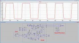
Distortion is in the ppm range, and the reproduction of a square wave, from an anti riaa network is shown below, not too bad I think !
To keep the design as much DC coupled as possible, a servo was used keeping offset in the mV range.
When using a sound processor, it will be possible to choose between the output from the first stage and do the remaining time constants digitally, or take the second stage without the need of further processing.
Hope you like it, comments welcome.
Hans
This version can be used in combination with a sound processor, in that case also receiving it's power through the phantom XLR connection.
But it can also be used independently, in that case either needing +/- 9V from batteries or from a mains supply.
Because phantom only produces a positive supply, the negative supply is made on board with a simple low cost switched capacitor converter, operating at 50kHz, far away from audio, but still not producing the EMI interference from a buck converter.
And because of this converter, it is also possible to feed the circuit with a single positive supply. All options are open.
Aurak is composed by two stages. The first stage shifts the pole from cart plus resistor from 500usec to 75sec, being already T3 of the Riaa curve.
The second stage takes care of T1 and T2 resp, 3180usec and 318usec.
There is also a T4 at 3.18usec, that was inserted between the two stages with 2k2/1n5.
To improve SNR I have increased gain of the first stage by 20dB and transferred the 3.18usec filter to the second stage.
A strap can switch this option on and off.
Because the original Rf in the second stage (200 Ohm) is part of T2 and T3, I have rearranged the inputs, now with Rf as a direct input from the first stage.
The benefit is that this resistor in no longer part of T1 and T2 and can be changed when a different overall gain is needed, without having to recalculate the filter component.
Overall gain is set at 45dB@1Khz, a value that will do in most cases.
Speaking of SNR, now being 600nV from 20Hz to 20Khz, or the equivalent of 4,25nV/rtHz or a SNR of 78.4dBA with the cart connected.
Op amps used are the OPA1642, very fast low noise Fet duals that only consume ca. 2mA/amp low enough to be powered by the Phantom line.
Distortion is in the ppm range, and the reproduction of a square wave, from an anti riaa network is shown below, not too bad I think !
To keep the design as much DC coupled as possible, a servo was used keeping offset in the mV range.
When using a sound processor, it will be possible to choose between the output from the first stage and do the remaining time constants digitally, or take the second stage without the need of further processing.
Hope you like it, comments welcome.
Hans
Attachments
Yes It’s for the Shure M97xE and it’s R=3*L-Rc see second and third link I posted.George,
This may have been a version where you needed a different math than R=2*Lc-Rc, could that be the case ?
In that case everthing gets different.
Hans
Thank you for the new version.
I think that LD and you should agree to have a thread for the Aurak preamplifier.
Contributions of both of you on this are now spread in time all over the place.
If you decide on a dedicated thread, I can provide a helping hand. If you want, just ask.
George
Yes It’s for the Shure M97xE and it’s R=3*L-Rc see second and third link I posted.
Thank you for the new version.
I think that LD and you should agree to have a thread for the Aurak preamplifier.
Contributions of both of you on this are now spread in time all over the place.
If you decide on a dedicated thread, I can provide a helping hand. If you want, just ask.
George
Thank you George, I think it’s a good idea to start an Aurak thread, but still a bit depending on what the others think.
- Status
- This old topic is closed. If you want to reopen this topic, contact a moderator using the "Report Post" button.
- Home
- Source & Line
- Analogue Source
- Cartridge dynamic behaviour