Hi Jack,Gonna try outboarding this for the HP3577 and Bode100
Allow me to give you a simple tip.
With 50 Ohm for R19, the equivalent input noise at R19 for a 10Hz filter @3Khz and with the OPA2604 will be 38nV.
For a SNR of 35dB to give an accurate measuring result, the Signal will then have to be 2.1uV at R19. With this 50 Ohm resistor, voltage over the Cart will then be 400uV.
When replacing R19 by a 5K resistor, equivalent noise wil be 46nV with a 10Hz filter. For the same 35dB SNR you will need 2.6uV signal at this spot.
However signal over the cart will now be 5 uV, or 80 times lower as with the 50 Ohm resistor.
Your 3577 will calculate a wrong Inductance for the coil, that only has to be corrrected with a factor 100.
Hans
I have got usable results, showing no impedance or phase changes at all with the source at -50dBU, which means -80dBU at the sense resistorHi Davidsrsb I've been waiting to find time to properly work through your recent stuff, and still not there yet. Every encouragement, the action begins perhaps -30dB below that, if it happens at all, IMO. Appols if already covered.
LD
I have got usable results, showing no impedance or phase changes at all with the source at -50dBU, which means -80dBU at the sense resistor
Hi David,
Great results so far, already down at ca 60uV on the Cart.
If possible, could you show the same recording as in #470, but now for the -80dBu at the sense resistor recording.
I’m especially interested in how much more noise there is on the curves compared to the earlier recording at -40dBU.
Hans
Gonna try outboarding this for the HP3577 and Bode100
Jack,
Your design probably still needs suitable output caps, because DC going to the 3577 should be avoided.
The 2604’s offset can be as high as 5mV.
That’s 500mV DC at the output with 40dB gain 🤗
A -80dBU measurement.Hi David,
Great results so far, already down at ca 60uV on the Cart.
If possible, could you show the same recording as in #470, but now for the -80dBu at the sense resistor recording.
I’m especially interested in how much more noise there is on the curves compared to the earlier recording at -40dBU.
Hans
Again impedance is scaled by 1/5, so the maximum value is really 50k
I used 2M samples, 4M gets an out of memory error on a 8GB PC
The TLV2372 is a noisy opamp, the only rail to rail I had to hand.
Also a metal box would be a good idea.
Attachments

Hi DavidA -80dBU measurement.
Again impedance is scaled by 1/5, so the maximum value is really 50k
I used 2M samples, 4M gets an out of memory error on a 8GB PC
The TLV2372 is a noisy opamp, the only rail to rail I had to hand.
Also a metal box would be a good idea.
Impedance is calculated as: Rsense*V(r)/(V(a)-V(r)).
V(a) and V(r) both being contaminated with noise of a certain percentage.
When V(a) and V(r) in the denominator are coming close, the error in the calculation of Z becomes bigger and bigger.
That's what I think that can be seen in your image.
The higher the frequency, the closer V(a) and V(r) become and the higher the noise in the calculation.
Say V(a) is 100 and V(r) is 95, both carrying +/-1% noise.
V(r)/(V(a)-V(r)) may now vary between 94/(101-94) and 96(99-96), or between 658 and 288. The original error of 1% has now become +/-39%.
The only remedy to keep the voltages apart, is to increase Rsense.
This won't increase the noise, because your Cmos amps will stay to be the dominant noise contributors.
So my question is to prove the theory and to get a more accurate measurement, could you repeat the measurement with Rsense 20K or even 50K.
Hans
Thanks Hans.
Am considering using the ADA4817 which is a single with 4nV/Rt Hz noise, and using the headers to adjust the gain via parallel resistors. ADA4817 is very high bandwidth so needs particular attention to layout.
Yes, the HP3577 is not happy with DC on the input. The Bode 100 is more tolerant.
Am considering using the ADA4817 which is a single with 4nV/Rt Hz noise, and using the headers to adjust the gain via parallel resistors. ADA4817 is very high bandwidth so needs particular attention to layout.
Yes, the HP3577 is not happy with DC on the input. The Bode 100 is more tolerant.
A -80dBU measurement.
Thanks David.
As you’ve said, your 0dBu is 0.75Vrms.
Accordingly, –80dBu is 75uV.
For the G1025 (Sensitivity 6.5 mV +/-1.5 dB, 1 kHz @ 5 cm/sec) this corresponds to a signal level close to 40dB below the recording reference level of 5cm/sec.
This is adequately low, no need IMO for going lower.
George
I probably influenced LD, as I raised the possibility of Permalloy saturation and eddy current losses to explain the typical MM ~5kHz dip. So far I have found that the Goldring magnetics seem innocent. Other brands I cannot confirm one way or the other
LD explained it in one of the other threads better than my simple observation that playing an LP at 0 volume still is easily audible so there is a lot of mechanical energy transmitted up the whole chain. He explained the midrange dip in terms of a very low Q dip in response due to mechanical issues and it seemed good to me until someone comes up with a better explanation. A 45mH Grado has the same dip even in their data sheet (a dB worse in my arm).
Last edited:
Except that we have measurements of the same generator with different phono stages, some with dip some without.
Moving magnet phase shift has some plots (with unknown test record accuracy) that seem to show dip then peak and yet I can show almost totally flat responses from similar generators.
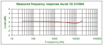
For example attached from LD's own measurements. Ok maybe 0.5dB down at 10kHz which is a lot less than most other measurements show. Sigh. I think we are back to the accuracy of the test record being as large as the effect we are measuring...
Moving magnet phase shift has some plots (with unknown test record accuracy) that seem to show dip then peak and yet I can show almost totally flat responses from similar generators.
For example attached from LD's own measurements. Ok maybe 0.5dB down at 10kHz which is a lot less than most other measurements show. Sigh. I think we are back to the accuracy of the test record being as large as the effect we are measuring...
Attachments
In #486 was tried to explain that depending on the ratio of Vr and Va, the error in calculating Z for the topology that David was using becomes bigger and bigger, the closer Va/Vr comes to 1 .
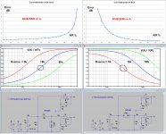
Just out of curiosity, I investigated this a bit in more detail for two topologies:
1) The Cart from Va to Gnd with a resistor Rs between Vr and Va, giving Z= Rs*Va/(Vr-Va)
2) the Cart between Vr and Va, with a resistor Rs from Va to Gnd, as in a Network analyzer. In that case, Z= Rs*(Vr-Va)/Va
Because I couldn't simulate the cumulated noise error calculating Z in LTspice, like in the image that David showed, I did the calculation in Excel.
I my calculation, I used a SNR of 40dB in both voltages Va and Vr.
As can be seen in the top two Excel images, to get the calculation of Z within 1dB starting the original 40dB SNR, the ratio of A/R should be ca. 50%.
But note that the two topologies are reacting in opposite directions.
I simulated the A/R ratio for 3 different R values, resp. 5K, 16k and 50K for the two topologies.
The get a 50% A/R ratio, the left topologie should use a minimum for Rs of 16K and the one at the right of no more than 5K to get the error in calculating Z below 1dB@3kHz as can be seen in the images below.
At this spot the voltage on the Cart will be the lowest for both versions.
Just to get some data, I used OPA1652 low noise Fet amps and started with with a SNR of 40dB@3Khz at output A.
After a 1/3 oct filter leaving 25uV noise, I needed therefore a 2.5mV@3Khz signal. Voltage on the Cart now was in the grounded Cart version 25uV and in the other version 15uV.
To conclude, from a perspective of also being able to investigating higher frequencies, the non grounded Cart version on the right is to be preferred over the grounded Cart.
And of course when narrower filters will be used, voltage on the Cart can even drop accordingly.
Hans
Attachments
Sigh. I think we are back to the accuracy of the test record being as large as the effect we are measuring...
Yes those guys ran the CBS LP's at 45rpm. The "same" means the same everything or it is a large collection of meta-data.
I generally trust the STR-112 results, they use no equalization on either end and the LP was not made with anything but highly technical users in mind. Accounting for a -2dB dip with electrical effects and a 45mH motor generates absurd numbers.
Just out of curiosity, I investigated this a bit in more detail for two topologies:
Just on time.
In a few days I am planning to start testing some cartridges again and this is a good help as I was wandering which topology is best to implement.
Thank you Hans.
George
That is true, you will get both better SNR and the sensitivity to gain errors between L and R, but you are on your own processing the metadata.To conclude, from a perspective of also being able to investigating higher frequencies, the non grounded Cart version on the right is to be preferred over the grounded Cart.
And of course when narrower filters will be used, voltage on the Cart can even drop accordingly.
Hans
This is good, and bodes well for TI loading.I have got usable results, showing no impedance or phase changes at all with the source at -50dBU, which means -80dBU at the sense resistor
LD
I still haven't had time to properly go over Davidsrsb's good works, but think I accept it. It's good news after all.@ LD,
It was you who came with the idea to investigate whether inductance is dependant on signal level for an MM Cart.
Question is now, has this been answerred to your satisfaction with proper accuracy and low enough level ?
Hans
LD
Hi David,That is true, you will get both better SNR and the sensitivity to gain errors between L and R, but you are on your own processing the metadata.
You are right, but when using a much higher Rsense as the 5K1 resistor that you mentioned, you would most likely get a much better result without sacrificing sensitivity and still being able to using your existing rig.
The only difference will be that you have to offer a larger input signal to get the same ca. 70uV on the cart at 3Khz as before.
I would still welcome to see your test Cartridge dynamic behaviour, now done with Rsense of minimal 50K or even higher.
Hans
- Status
- This old topic is closed. If you want to reopen this topic, contact a moderator using the "Report Post" button.
- Home
- Source & Line
- Analogue Source
- Cartridge dynamic behaviour