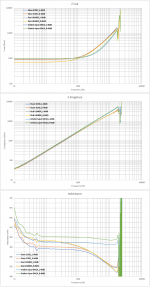
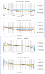
Impedance sweep measurements of the three cartridges.
-9dB=456mVrms across the DUT
-40dB=12.9mVrms across the DUT.
There is good agreement btn results of the sweeps and the LCR meter readings.
George
-9dB=456mVrms across the DUT
-40dB=12.9mVrms across the DUT.
There is good agreement btn results of the sweeps and the LCR meter readings.
George
Attachments
-
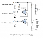 1 Schematics of actively buffered impedance measuring jig.PNG23.7 KB · Views: 152
 -
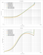 2 modulus, phase-9dB.png135.2 KB · Views: 147
 -
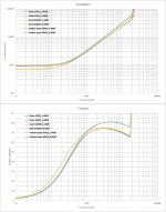 3 modulus, phase-40dB.png113.7 KB · Views: 139
 -
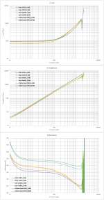 4 real, imaginary, impedance -9dB.png169.9 KB · Views: 147
 -
 5 real, imaginary, impedance -40dB.png169.7 KB · Views: 163
 -
 6 errors diagram.png133.5 KB · Views: 67
 -
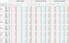 7 comparative measurements.png93 KB · Views: 60
George,
What a fantastic job you did.
I know how much time it takes to get everything properly organized in images and tables.
My question to you is, what in your measuring chain sets the limit in frequency.
The reason I ask is because when trying to construct a model for a Cart, it becomes obvious that the dip in the inductance and hence in the FR around 15kHz is greatly affected by properties in the region from 20kHz to 100kHz.
So would it be possible to get some more data in that area?
If you would need a 192k/24 .Wav file with a sweep up to 80kHz, I would be happy to send you one.
Hans
Thank you Hans.
The bottleneck is my soundcard, an aged M-Audio Audiophile USB.
In duplex mode it works only up to 48kHz sample rate.
Thus, theoretical test limit is 24kHz. With weak signals practical limit is around 18kHz, the weaker the signal the lower the frequency limitation.
For the high frequencies I have to revert to manual spot frequency testing. Bench signal generator as a source, monitor the two outputs of the test jig with oscilloscope, log measurements, practice Excel and post (work for next week).
As you understand Bill, what worries you it doesn’t have to do with the cartridges. It is measurement limitation. It does it with the calibration resistors too
George
It ought not to happen with real resistors R + 0j.As you understand Bill, what worries you it doesn’t have to do with the cartridges. It is measurement limitation. It does it with the calibration resistors too
It think Bill's point is that using phase to determine the 'real' part of impedance doesn't describe reality very well. Self-resonance of the coil, as an LC system, will show phase deviation from pure inductance versus f ie becomes more real toward resonance. But that is not due to 'real' resistance, in the sense it is not lossy and cannot dissipate energy.
I think that could be what is measured here, and showing up as 'reduced inductance'. The crux issue is whether inductance in the sense of 'ability to induct' has been affected, because that is the generator element function. I think it probably isn't affected in these tests: all that happens is energy is passed between self C and self L, and the phase/amplitude response of the LCR system overall is the product of that.
What one needs to do is isolate the 'real' resistance of the coil, probably as a power transfer function somehow ?
LD
As you understand Bill, what worries you it doesn’t have to do with the cartridges. It is measurement limitation. It does it with the calibration resistors too
George
Thanks George, thought it might be something like that. I clearly need to build my own rig as well to experiment. I need to go away and look some more at the numbers you have to see what can be picked out. Thank you for doing these.
What can only be measured / calculated this way is the reactance, and only by building a model replicating Re, Im and phase will it become possible to get (or at least approximate) the values of all the individual components.I think that could be what is measured here, and showing up as 'reduced inductance'. The crux issue is whether inductance in the sense of 'ability to induct' has been affected, because that is the generator element function. I think it probably isn't affected in these tests: all that happens is energy is passed between self C and self L, and the phase/amplitude response of the LCR system overall is the product of that.
LD
But the faith of every model is, although very helpful in helping to better understanding things, one can never prove that it is correct.

Hans
George,Impedance sweep measurements of the three cartridges.
-9dB=456mVrms across the DUT
-40dB=12.9mVrms across the DUT.
There is good agreement btn results of the sweeps and the LCR meter readings.
George
From almost a few hundreds of Herz and downwards, the inductance shown in your images is going upwards.
I see no physical reason why this should happen, so there may have been some inaccuracy creeped into your test rig.
Hans
It ought not to happen with real resistors R + 0j.
It think Bill's point is that using phase to determine the 'real' part of impedance doesn't describe reality very well. Self-resonance of the coil, as an LC system, will show phase deviation from pure inductance versus f ie becomes more real toward resonance. But that is not due to 'real' resistance, in the sense it is not lossy and cannot dissipate energy.
I disagree with that, the real part of the impedance will have noise and has to dissipate energy anything else is thermodynamically impossible.
Scott,Speaking of which, I've been playing with my code to do the frequency sweep as a single huge transform. The regular wiggles here at the low end are warp and eccentricity, at the high end it seems that surface noise starts to hurt (there is no averaging). This is 500Hz to 40kHz (40-48kHz was mostly noise), arbitrary dB reference. This is the CV sweep no equalizations.
There is a discrepancy between various images that I don't understand.
You played a CV track through a flat preamp. Ideally this should have resulted in a flat FR up to or near 20kHz, true ?
But there is a -3dB dent in the FR between 5 and 6kHz.
However, when looking at the FR that you made with the Adjust+ record
Cartridge dynamic behaviour
there is no such dent.
To make it easier for the eye, I compared the FR of your Cart to mine from the same track, where my element was used as a reference.
Cartridge dynamic behaviour
And again, no such dent, but this time a 4 to 5dB peak at 12kHz, that is not visible in your CV recording.
Was this one and the same Cart ? If not, what is causing these large differences.
Hans
Was this one and the same Cart ? If not, what is causing these large differences.
No idea, except that there are decades and lots of change in technology between the LP's, don't know which to trust as references.
No idea, except that there are decades and lots of change in technology between the LP's, don't know which to trust as references.
Since this thread for the most part concentrates on the properties of a Moving Magnet Cart, isn’t the best possible reference created with a Cart that largely exceeds the frequency response of an MM Cart ?
That was the reason for my contributions to this thread as an attempt to create such references.
Without well accepted referenced LP’s it’s very hard to investigate MM properties in more detail as became obvious with the FR from the CV recording, showing unacceptable deviations of -3dB to +5dB.
Hans
Without well accepted referenced LP’s it’s very hard to investigate MM properties in more detail as became obvious with the FR from the CV recording, showing unacceptable deviations of -3dB to +5dB.
I was initially interested in Bill's questions about whether the midrange dip is not there on some MM carts or a little of it is always there. Even the published Grado charts have it, BTW you usually spec the average deviation +-1.5dB not 0 -3dB. Considering the CBS LP's were made under laboratory conditions I am not ready to say the CV track is at fault. The PN problem is possibly a fault of the 60's technology.
I double checked my pre-amp yesterday and it still is at +-0.1dB. I'm not a great believer in simple frequency response deviations making the most important difference in listening, but as a project to share it made sense to do that. I seems a lot to ask from a cartridge to be anywhere near that so where do you draw the line. I suspect that if most folks put a well calibrated B&K dummy head at their preferred listening position they would be stunned by what they see for response.
Or -3dB@5kHz and +5dB@12kHz for that matterI was initially interested in Bill's questions about whether the midrange dip is not there on some MM carts or a little of it is always there. Even the published Grado charts have it, BTW you usually spec the average deviation +-1.5dB not 0 -3dB.
I'm also highly surprised by the outcome of the CBS record.Considering the CBS LP's were made under laboratory conditions I am not ready to say the CV track is at fault. The PN problem is possibly a fault of the 60's technology.
But when a CH Precision PN record going to 30kHz is showing a perfect 3dB/oct line up to 30kHz within +/-0.5dB and when an Adjust+ record gives the exact same outcome with a sweep as with PN, isn't that conclusive enough to be used as references ?
How many references does one need ?
Hans
No, because one does not know that the source was not 'tuned' to provide such results, nor that it isn't happy coincidence. One has to start somewhere, and that could equally be to assume that good cartridge playback is flat and minimum phase, and calibrate a record to that.... which may or may not be true in an absolute sense.But when a CH Precision PN record going to 30kHz is showing a perfect 3dB/oct line up to 30kHz within +/-0.5dB and when an Adjust+ record gives the exact same outcome with a sweep as with PN, isn't that conclusive enough to be used as references ?
The test records I have most confidence in, because of the pedigree of Decca engineering at the time, are the spots and sweeps from Decca's SKL and SXL test records from the late 50s/early 60s. These are the test records that produce flat response from an OM40 and Aurak over the audioband. Whether that is absolute, is very difficult to prove.
A plausible scenario for the DIYaudio test record is that we would have applied a flat source, measured what was actually obtained from consensus on good rigs, and then 'corrected' the source so the result obtained by consensus was flat in a 2nd pressing iteration. But that's not an absolute reference. Trust you can see the difference.
LD
Last edited:
The bottleneck is my soundcard, an aged M-Audio Audiophile USB.
Hi George,
You are always providing a tremendous amount of data which you have spend considerable amount of time of collecting.
I would like to support that. What operating system are you running? I'm willing to send you a EMU-0404 I have which I never use. If you think you can workaround the driver issue let me know.
Cheers,
Mogens
Or -3dB@5kHz and +5dB@12kHz for that matter
I don't understand, the plot I posted was 76dB at 500Hz and 76dB at 12kHz and 73dB at 5kHz +-1.5dB.
- Status
- This old topic is closed. If you want to reopen this topic, contact a moderator using the "Report Post" button.
- Home
- Source & Line
- Analogue Source
- Cartridge dynamic behaviour