My turntable rested on a plinth. Under the plinth I put 4 small mylar balloons to level the contraption. Each mylar balloon had a inner tube shraeder valve, ( the air valve) inserted into the neck of the balloon. Each was independently adjustable and it didn't leak.
have fun as a tweaker
have fun as a tweaker
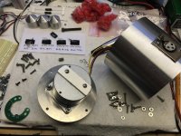
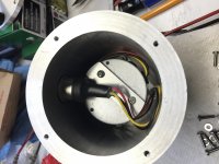
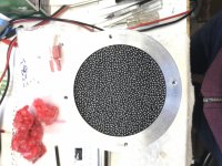
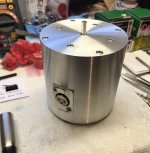
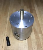
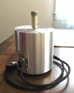
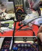
Here I fabricated a plate to cover small openings on the bottom of the motor where the hall sensor mounted. I was concerned some lead shot might get inside. I also had to figure out a way to seal up the wiring to prevent any shorting. As I mentioned, the motor connection had to be reworked due to clearance issues. The XLR connection got scraped. The final version required that I machine a recessed pocket. I modified and mounted a mic connector that was shortened and an elbow added to route hard wiring that is soldered and shrink wrapped inside the pod. The mic connections this end is really just functioning as a clamp.
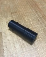
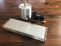
I also had to fabricate a pulley for it. The Delrin version wasn’t concentric enough. There was a lot of teeth grinding along the way, and several unsatisfactory attempts. My old Logan lathe didn’t have the tolerance capabilities that I wanted, but eventually I got something usable.
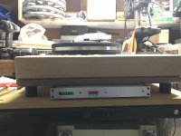
The last pic is the final version being used.
I also had to fabricate a pulley for it. The Delrin version wasn’t concentric enough. There was a lot of teeth grinding along the way, and several unsatisfactory attempts. My old Logan lathe didn’t have the tolerance capabilities that I wanted, but eventually I got something usable.
The last pic is the final version being used.
Attachments
-
 B3C77D95-5714-4552-BD73-95F3ACA9BB9F.jpg952.4 KB · Views: 373
 -
 F111F45A-DD84-47B9-83BB-03E8A5C3832B.jpg815.4 KB · Views: 364
 -
 822F0E1D-36CC-4725-AEB3-A66B95136A7D.jpg859.8 KB · Views: 351
 -
 BCF70A09-CA15-4407-840F-F731D69C9D3A.jpg471.8 KB · Views: 344
 -
 9B84BDA8-F04D-47B1-9C8F-38EF579B9DBA.jpg486.7 KB · Views: 170
 -
 B2613A47-9C58-4E6D-A4D5-1594E30724CE.jpg451.9 KB · Views: 349
 -
 3807852F-EA7E-4B6D-9CFD-2B47D97BF64A.jpg370.3 KB · Views: 194
 -
 DD32647E-0CF8-41BE-A927-E2B516EC380B.jpg1 MB · Views: 232
My turntable rested on a plinth. Under the plinth I put 4 small mylar balloons to level the contraption. Each mylar balloon had a inner tube shraeder valve, ( the air valve) inserted into the neck of the balloon. Each was independently adjustable and it didn't leak.
have fun as a tweaker
Can you post some pictures?
Thanks very much Packgrog. Building things is really what I love to do.
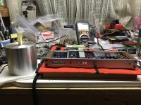
I do not have an elaborate shop...everything is sort of jammed into spaces in my garage and basement.
I was lucky enough to find a very old Logan lathe 3 or 4 years ago on Craigslist cheap. I had wanted a lathe forever. The owner was moving cross-country and didn’t want to have to take it. It’s missing a tooth on the back gear and as I mentioned has trouble holding high tolerances. It probably needs the headstock rebuilt.
My mill is a cheap Chinese made Grizzly bench top unit I also found used on Craigslist. The build quality is suspect and it already is having some issues with bearings in the head. I will probably have to tear out the gear drive system and convert it to belt drive soon.
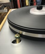
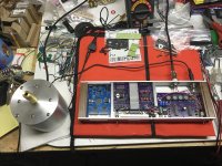
Here is a pic where I finally got the plinth in place on the base with the platter mounted.
I’m testing to see if I’ve managed to maintain enough clearance and alignment with the platter to have the option of rim driving it.
I had already gone back in and re-worked the suspension by shortening the threaded inserts and bushings that support the plinth more than once.
Having the motor underneath the plinth made matters very difficult. The longer the pulley had to be the worse the tolerances were in trying to keep it concentric.
I do not have an elaborate shop...everything is sort of jammed into spaces in my garage and basement.
I was lucky enough to find a very old Logan lathe 3 or 4 years ago on Craigslist cheap. I had wanted a lathe forever. The owner was moving cross-country and didn’t want to have to take it. It’s missing a tooth on the back gear and as I mentioned has trouble holding high tolerances. It probably needs the headstock rebuilt.
My mill is a cheap Chinese made Grizzly bench top unit I also found used on Craigslist. The build quality is suspect and it already is having some issues with bearings in the head. I will probably have to tear out the gear drive system and convert it to belt drive soon.
Here is a pic where I finally got the plinth in place on the base with the platter mounted.
I’m testing to see if I’ve managed to maintain enough clearance and alignment with the platter to have the option of rim driving it.
I had already gone back in and re-worked the suspension by shortening the threaded inserts and bushings that support the plinth more than once.
Having the motor underneath the plinth made matters very difficult. The longer the pulley had to be the worse the tolerances were in trying to keep it concentric.
Attachments
Yeah, I'm in a condo. No room for a shop like that even if I had the cash for equipment.
Interesting your desire to try rim drive. With your mass-loaded/damped motor pod and DC motor that may well work nicely. I'd be interested to know your listening impressions between trying as rim drive vs. belt drive. Also your impressions of differences based on the number of belts (rim or belt-style). Any rim drives I've seen have only had one contact "belt", and I've read that 2 belts seems to be the sweet spot for most belt drives. I'd love to try it myself, but I can't even get a single speed multi-groove pulley made for my Hurst 600RPM motor.
Loving your project results, though! Looking forward to further updates!
I'll try and leave commentary/impressions to the end...I will say that I had unacceptable speed stability issues relating to the use of 2 newer black drive belts that I had on hand from VPI. They were too long and the rubber compound was not as good as the original drive belt that came with my HW19.
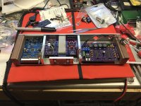
As usual, I had to complicate things by adding additional requirements to the motor control system.
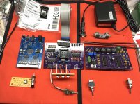
I decided I wanted the case that held the controller electronics to maintain a very low profile that matched that of the Falcon and Roadrunner cases so that it would be able to tuck into the space below the base of the turntable.
This requirement alone added many hours of fabrication, trial/error fitting and also required creativity with mounting some components to reduce the profile of the assembled sine wave generator and amplifier boards. Getting clearance for all the switches, displays, plugs and wiring in the case was like a contortionist act.
I had intended to implement a separate rotary encoder for some of the functions of the SG4 on the front of the case, but the idea got scrapped due to space limitations and the fact that I wanted to have easy access to all SG4 functions from the front panel in case I needed to make adjustments while trying the controller with different tables or motors.
The board for the tactile switches that I remote mounted got a little simpler when I found out I only needed to run one ground to share on the board and another single wire to each switch. Building the support for the display and switch board along with fabricating the button assembly and getting it to work and look decent on the front of the case was down right tedious.
To make things even more fun, I decided I wanted to integrate my Roadrunner into the same case and have everything powered off of only one power supply connection to the case.
The LED displays didn’t match in color or intensity and were too bright for my taste. I had an extra acrylic welding goggle lens in the garage which I cut up carefully and shaped so that I could slide them into the case in front of the displays to dim them a bit and even out the lighting.
Not too many pics...I guess I was bogged down by the process...but you get the idea.
Attachments
-
 1AD048AD-CD21-4718-8A0B-C77777961855.jpg1,017.2 KB · Views: 225
 -
 4F66BB80-ADFB-4C15-91FD-C9DE2143C242.jpg514 KB · Views: 223
 -
 777ED511-FA8F-4365-86FA-B77C93CEEF74.jpg997.2 KB · Views: 223
 -
 360F8185-2BA2-44F1-87FB-11EDFD7D0BDC.jpg664.1 KB · Views: 183
 -
 7A91C943-0BFF-4705-889E-6C0806BAD282.jpg1 MB · Views: 194
 -
 24142512-7829-4A46-86F2-B3719EFCE30A.jpg879.4 KB · Views: 222
 -
 C5B40460-E617-4D94-9EAA-59E23A2160CF.jpg1,021.4 KB · Views: 204
Thanks very much coolmaster. I would love to be able to help people out with their projects. I’ve had several members contact me about pulleys and motor pods. The problem is that I’m not a professional machinist and it was quite a struggle and very time consuming to get these results with the old equipment I have.
I have thought many times that it would be great to try and make some money from this hobby. The problem is that once you start trying to do that you seldom have time to enjoy the hobby yourself.
Most of my experience is in the fabrication end of these projects rather than the electronics. My background is in the arts. So I guess I look at these projects from a more creative point of view or as a frustrated artist. It might be cool to be able to do some commissions at some point...but I doubt it would be lucrative.
<snip> It might be cool to be able to do some commissions at some point...but I doubt it would be lucrative.
It's mostly a matter of finding the right people, commissions can be a way of covering some of the cost of the hobby. You have mad skillz and there are few who can match your workmanship.
I need to have some small parts done from time to time and don't have the space to have my own milling machine and lathe. I have to use outside resources. Some of people have nice CNC machines, but setting up fee is very expensive. So, for diyers like us, if someone has excellent skills with manual machines and fee is reasonable, that is ideal. Luckily I did find a gentleman in CT. He did serval small parts for my air bearing arm. I am very happy about it.
Thanks very much coolmaster. I would love to be able to help people out with their projects. I’ve had several members contact me about pulleys and motor pods. The problem is that I’m not a professional machinist and it was quite a struggle and very time consuming to get these results with the old equipment I have.
I have thought many times that it would be great to try and make some money from this hobby. The problem is that once you start trying to do that you seldom have time to enjoy the hobby yourself.
Hello Chromenuts,
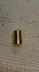
No worries. I'm located at South East Asia, a long way from you folks in USA. I have access to a fairly good machinist at my location which I've used them to make various custom self designed mod parts for my turntable that enhanced my tt performance to another level. It would be very costly to have someone fabricate it in the States and shipped to me, far too costly for me to import anything of heavy mass or size. My most recent implementation was a solid brass custom pulley for my VPI. I had to design the pulley from scratch as my pulley is a very different diameter from USA models. Mine is 0.755" diameter for 500rpm to 33.33 rpm, but resulted in a bit slower than required in practice. This sample was my first prototype. I may attempt a revised version sometime in future, if my machinist is able to fabricate it with higher precision. My pulley works very very well in practice but there's some tiny degree of inaccuracy at each step. I wish it was ideal but its near enough for purpose and intent. The SG4 speed controller easily compensated to the speed I want.
I've not given great thought (or doing anything yet) about customizing the motor pod shape and dimensions to my own preference and suitability to the existing motor, but after seeing your product, its a strong encouragement to do something on my own from here, IF the machinist is able. There's so many variables and design parameters I've to deal with, such as 1 or 2 phase connectivity, the height, the mounting details to suit the VPI Hurst motor, kind of feet or base that looks cool, etc, etc. Till I have and decide what I really want, I could draft a drawing to the machinist for a quotation. I'm certain to show it here if and when it does happen.
Best regards,
Lee.
Attachments
Last edited:
It’s always interesting to hear about how others find their way in this hobby. Sometimes I feel like it occupies a bit too much space in my head. I do like that fact that I am always trying to learn something new through it.
@Super...I’m also in CT in a little area called Bunker Hill on the border of Watertown and Waterbury. If you don’t mind me asking, what part are you in?...and have you ever attended any audio related events locally, in New England or otherwise? I’ve read quite a bit on various tonearm threads and was very interested in building one of my own air bearing or Schroeder inspired arms hopefully soon. I need to sort out a bass solution for my horn project first.
@Super...I’m also in CT in a little area called Bunker Hill on the border of Watertown and Waterbury. If you don’t mind me asking, what part are you in?...and have you ever attended any audio related events locally, in New England or otherwise? I’ve read quite a bit on various tonearm threads and was very interested in building one of my own air bearing or Schroeder inspired arms hopefully soon. I need to sort out a bass solution for my horn project first.
Last edited:
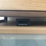
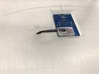
A final complication with integration of the drive control system was mounting of the hall sensor for the Roadrunner. I didn’t like the idea of sticking the sensor PCB onto the top surface of my plinth somewhere in plain sight with the wiring hanging from the side of the table.
I decided I wanted to mount the sensor PCB under the platter. The problem was that it had a fairly large audio style connection for the signal wire that was too big to fit under the platter even if there was clearance for the board.
I removed the signal jack from the sensor PCB and the plug from the signal wiring. After I confirmed polarity for the signal wires I soldered them directly to the sensor PCB and then potted the wiring connections with epoxy onto the board to stabilize and reinforce them.
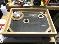
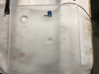
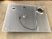
I picked a spot for the sensor at the back of the table and decided to run the signal wire straight through the plinth. I mounted the trigger magnet on the bottom of the platter. I traced a silhouette along the edge of the platter where I wanted the sensor board to be mounted on the plinth. I measured off of the silhouette line to make sure I would have the hall sensor centered at the same distance that the trigger magnet was mounted on the bottom of the platter. Then I laid out a recess and passage for the sensor board and wiring and machined them into the plinth.
The acrylic had to be removed for the process so that I could also drill through the steel sub-plinth and the lead damping layer. I took the opportunity to clean everything again well and added the layer of high quality black paper above and below the rubber coated lead to allow for easier positioning, removal and substitution of different damping materials as well as a uniform appearance through the frosted acrylic plinth.
When I first tested the system the hall sensor was not triggering properly. I ended up going back and having to recess the platter bearing flange into the acrylic to lower the height of the platter as much as possible along with shimming the sensor PCB back up slightly. I was under the impression that there was more flexibility concerning the gap required between the trigger magnet and hall sensor. I had to get it down to within a millimeter or so in order for it to work properly.
I decided I wanted to mount the sensor PCB under the platter. The problem was that it had a fairly large audio style connection for the signal wire that was too big to fit under the platter even if there was clearance for the board.
I removed the signal jack from the sensor PCB and the plug from the signal wiring. After I confirmed polarity for the signal wires I soldered them directly to the sensor PCB and then potted the wiring connections with epoxy onto the board to stabilize and reinforce them.
I picked a spot for the sensor at the back of the table and decided to run the signal wire straight through the plinth. I mounted the trigger magnet on the bottom of the platter. I traced a silhouette along the edge of the platter where I wanted the sensor board to be mounted on the plinth. I measured off of the silhouette line to make sure I would have the hall sensor centered at the same distance that the trigger magnet was mounted on the bottom of the platter. Then I laid out a recess and passage for the sensor board and wiring and machined them into the plinth.
The acrylic had to be removed for the process so that I could also drill through the steel sub-plinth and the lead damping layer. I took the opportunity to clean everything again well and added the layer of high quality black paper above and below the rubber coated lead to allow for easier positioning, removal and substitution of different damping materials as well as a uniform appearance through the frosted acrylic plinth.
When I first tested the system the hall sensor was not triggering properly. I ended up going back and having to recess the platter bearing flange into the acrylic to lower the height of the platter as much as possible along with shimming the sensor PCB back up slightly. I was under the impression that there was more flexibility concerning the gap required between the trigger magnet and hall sensor. I had to get it down to within a millimeter or so in order for it to work properly.
Attachments
When I first tested the system the hall sensor was not triggering properly. I ended up going back and having to recess the platter bearing flange into the acrylic to lower the height of the platter as much as possible along with shimming the sensor PCB back up slightly. I was under the impression that there was more flexibility concerning the gap required between the trigger magnet and hall sensor. I had to get it down to within a millimeter or so in order for it to work properly.
Hi,
Within a millimeter to get it working is perplexing. That's very close.
I used a coin magnet (assumed as strong neodymium type) measuring 13mm x 1.5mm (did try another thicker one which also worked), the gap is more than a few mm (possibly 5mm thereabout?), it triggers fine. I have to ensure the magnet is the correct direction facing the sensor and will pass over the it for effect.
The sensor should work with the magnet up to ~1/4" away. Make sure the magnet passes directly over Q1 on the sensor PCB, and also verify the correct pole (flat side) of the magnet faces the sensor; Q1 only responds to one pole of the magnet.
That being said, the closer the magnet, the more consistent the trigger seems to be.
That being said, the closer the magnet, the more consistent the trigger seems to be.
The sensor should work with the magnet up to ~1/4" away. Make sure the magnet passes directly over Q1 on the sensor PCB, and also verify the correct pole (flat side) of the magnet faces the sensor; Q1 only responds to one pole of the magnet.
That being said, the closer the magnet, the more consistent the trigger seems to be.
Hi Bill. I was very careful about alignment of the magnet and hall sensor. I rechecked it several times.
I discovered that only one side of the magnet triggered the sensor by holding it with tweezers and passing it close to the sensor while confirming it was triggering by observing the display on the Roadrunner before I mounted it.
I still had to get the magnet and sensor gap much closer than 1/4”. As I said it is probably 1mm and change definitely not over 2mm. I’m starting to suspect that I didn’t get an original magnet with the Roadrunner. I bought it used.
Were people supposed to source their own magnets? It is much smaller than coolmaster and other people have said they are using. Probably a 1/4” diameter at most and maybe 1mm thick or so.
Either way, it seems to be working perfectly now and I am happy. The tight tolerance between the platter and plinth looks much better than having it float 1/4” high.
Last edited:
- Status
- This old topic is closed. If you want to reopen this topic, contact a moderator using the "Report Post" button.
- Home
- Source & Line
- Analogue Source
- VPI resto-mod...a tale of bastardizing my HW19