Hi
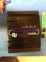
I have a faulty phono amp that has seen little use and been sitting around in a drawer for a year. It is an Art Accessories DJ PREII.
The right channel has stopped working.
When putting a 1khz sine wave through the amp I can see the signal with a scope on the left channel but not the right, just ripple and noise. I cannot see any damage on the board. There is continuity at the phono socket.
The unit runs from a 9v wall wart.
Is there a another strategy to finding the fault, or is there a likely suspect component? I am not familiar with the circuit layout yet.
Thanks
Attachments
Also I would check the soldering around any 'high thermal mass' components, regulators, switches, phono connectors. From the photo some of them do not look too good. Flow soldered boards with SMT components suffer badly from this problem and they may take several years for faults to develop. Or PM me, send me the board (I'm in Melbourne) and I will try and fix it for you!
Check the rubber. It can be shortening a PCB trace Check also the switches for continuity. ... Use the scope to trace the op-amps. Have You tried swapping the phono leads ?
Fault is the same with pcb out of case. Capacitance switches have no effect. No other switches. Done the lead swapping.
Also I would check the soldering around any 'high thermal mass' components, regulators, switches, phono connectors. From the photo some of them do not look too good. Flow soldered boards with SMT components suffer badly from this problem and they may take several years for faults to develop. Or PM me, send me the board (I'm in Melbourne) and I will try and fix it for you!
I just resoldered all connections in the backside of the board. No change.
I have a temperature controlled out air gun. What temp should it be set for the lead free soldered SMT components?
Thanks for the offer. I’ll keep that ace up my sleeve for the moment ��
Last edited:
Dunk02
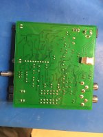
The rubber I meant is that shiny rectangular thing You see on the right side of the 3rd photo glued to the PCB. There is a PCB track that goes near the RCA's.
Apologies, the rubber made out of metal! Thought you mean’t the rubber on the case exterior. Am I looking for a broken track to the faulty channel caused by mechanical strain? I am not sure which track you mean.
")
I have probed the right channel output (100khz sine wave input) while stressing the board but nothing showed up.
The track I mean is under the edge of the "metal thing" As the "metal thing" is connected to ground and over the track ...
Why 100Khz ? Music goes up to 25 Khz. I would try something in the 1 Khz audible range.
You have lots of Vias (Holes) and one of them could be faulty. I would test them for continuity or perhaps fill them with solder.
But I bet it's one of the op-amps. Have You traced them already ? Feed You signal and then test at each outputs if there is a signal.
Whoops, meant 1000Hz.
The track you mentioned is pretty beefy and I checked continuity - OK.
I think the board is covered in a light conformal coating so don’t know if heat gun reflowing if surface mount components is viable.
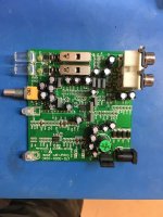
Testing opamps in circuit - that is a new technique I will have to learn. At the moment I am not entirely sure of the board topology. I can see the input power stage, some circuitry for LEDs, and three IC packages with lots of resistors and capacitors, and three transistors. Looks much more complicated than simple circuit diagrams I have seen. I presume the ICs are the opamps but cannot find a data sheet for them - ST GZ308.
The track you mentioned is pretty beefy and I checked continuity - OK.
I think the board is covered in a light conformal coating so don’t know if heat gun reflowing if surface mount components is viable.
Testing opamps in circuit - that is a new technique I will have to learn. At the moment I am not entirely sure of the board topology. I can see the input power stage, some circuitry for LEDs, and three IC packages with lots of resistors and capacitors, and three transistors. Looks much more complicated than simple circuit diagrams I have seen. I presume the ICs are the opamps but cannot find a data sheet for them - ST GZ308.
Last edited:
I just resoldered all connections in the backside of the board. No change.
I have a temperature controlled out air gun. What temp should it be set for the lead free soldered SMT components?
Thanks for the offer. I’ll keep that ace up my sleeve for the moment ��
First check the through hole large components. In particular the input output sockets as they have high thermal mass and are subject to mechanical stress. And that TO220 package which I assume is the regulator, of course if this is disconnected both channels would dead.
If you so see any dodgy SMT soldering set your iron to 260C and just locally retouch the joint.
if you put signal on both inputs, you should see signal (on a scope or small speaker ) on pins 1 and 7 if the chips are dual op amps. pin 6 if they are singles. both channels should be the same amplitude.
where the signal disappears is where a bad component is.
be sure to use a 100uf cap to the small speaker from ground
where the signal disappears is where a bad component is.
be sure to use a 100uf cap to the small speaker from ground
if you put signal on both inputs, you should see signal (on a scope or small speaker ) on pins 1 and 7 if the chips are dual op amps. pin 6 if they are singles. both channels should be the same amplitude.
where the signal disappears is where a bad component is.
be sure to use a 100uf cap to the small speaker from ground
Thanks. Are there three opamps in this board?
 Moved to analog source since this is a phono pre-amplifier. Many phono pre-amp mavens hang out here.
I have now found that the original 9V 1A transformer power supply has failed due to blown thermal fuse on the primary winding (the secondary winding is intact) . Perhaps this was caused by a short in the amp that has something to do with the loss on an output channel?
It could be related, but some additional trouble shooting is required. An op-amp with severe ESD damage might do this.
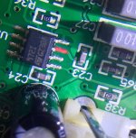
There are no markings in the chip to show which is pin 1.if you put signal on both inputs, you should see signal (on a scope or small speaker ) on pins 1 and 7 if the chips are dual op amps. pin 6 if they are singles. both channels should be the same amplitude.
where the signal disappears is where a bad component is.
be sure to use a 100uf cap to the small speaker from ground
Had another read on the web and have now done the following.
Applied dummy load to signal outputs.
Compared signal of the two op amps closest to the terminal on the board.
The one closest to the terminals is the right channel.
The Signal generator set to 1kHz, about 80mV rms.
First the left channel: 2.2v sinewave at pins 2, 3,4,6,7,8 (my numbering is from bottom right clockwise). Pin 1 0V, pin 5 4.7v
Right channel: 2.2v sinewave at pin 2. Pin 3, 160mV. Pin 4 and 5, 4.7V. Pin 6,7,8 2.2V. Pin 1 0V.
I have no training and little experience in electronics. Pretty much relying on my high school knowledge from many years ago, and a few years of tinkering.
I have read up on op amps but need help to interpret these results.
Last edited:
I guess it is a TS972ID dual opamp (datasheet for example in https://www.mouser.com/ds/2/389/ts971-957361.pdf ).
Correct numbering is always from bottomleft counterclockwise (that means that the red pin is pin3 - see p.3 of datasheet). This mean that pin 4 (your pin 1) is correct ground and pin 8 (your pin 5) is Vsupply (correctly 4.7 in your measurements). However I see that your measurements show signal on both opamps for left channel and only one channel for right channel (which seems to be clipping unlike the other channel). How do you check inputs/outputs, with a scope? The 2 opamp outputs are pins 1 (your 4) and pins 7 (your 6). Do they show sinewave output?
Correct numbering is always from bottomleft counterclockwise (that means that the red pin is pin3 - see p.3 of datasheet). This mean that pin 4 (your pin 1) is correct ground and pin 8 (your pin 5) is Vsupply (correctly 4.7 in your measurements). However I see that your measurements show signal on both opamps for left channel and only one channel for right channel (which seems to be clipping unlike the other channel). How do you check inputs/outputs, with a scope? The 2 opamp outputs are pins 1 (your 4) and pins 7 (your 6). Do they show sinewave output?
- Status
- This old topic is closed. If you want to reopen this topic, contact a moderator using the "Report Post" button.
- Home
- Source & Line
- Analogue Source
- Phono Pre-amp fault