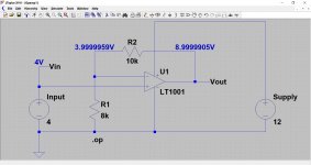
The golden rule for an opamp used in audio (which means it will have a normal feedback network wrapped around it) is the output will go to whatever voltage is needed to maintain the difference between the two inputs to zero (zero for practical purposes here).
See if this makes sense.
The opamp has 4 volts applied to the + input. In order to see if the rule works we need to get 4 volts on the - input and the opamp output will automatically do that for us via the feedback network...
Here's how:
4 volts across 8k means a current of 4/8000 has to flow. Just ohms law. We also know the opamp inputs draw no real current to affect things. So from that we can say that this same current must also be flowing in the 10k resistor.
If we do the maths we get 0.0005A in the 8k. Multiply that current by 8000 and we get 4 volts. Now multiply the same current by 10,000 and we get 5 volts. So the total voltage across the two resistors is 9 volts.
The working simulation bears that out.
We can then go on and say that the gain is actually 1+(R2/R1). Does that work ?
(10000/8000) + 1 equals 2.25
Multiply our input voltage of 4 volts by 2.25 and we get 9 volts.
So relating that to your fault, if pin 2 (the - input) is lower that pin 3 (the + input) and the opamp output is high (yours is) then we either have a duff opamp (and tbh that would have been my less likely option... but it happens") ), or something is pulling pin 2 down.
), or something is pulling pin 2 down.
See if this makes sense.
The opamp has 4 volts applied to the + input. In order to see if the rule works we need to get 4 volts on the - input and the opamp output will automatically do that for us via the feedback network...
Here's how:
4 volts across 8k means a current of 4/8000 has to flow. Just ohms law. We also know the opamp inputs draw no real current to affect things. So from that we can say that this same current must also be flowing in the 10k resistor.
If we do the maths we get 0.0005A in the 8k. Multiply that current by 8000 and we get 4 volts. Now multiply the same current by 10,000 and we get 5 volts. So the total voltage across the two resistors is 9 volts.
The working simulation bears that out.
We can then go on and say that the gain is actually 1+(R2/R1). Does that work ?
(10000/8000) + 1 equals 2.25
Multiply our input voltage of 4 volts by 2.25 and we get 9 volts.
So relating that to your fault, if pin 2 (the - input) is lower that pin 3 (the + input) and the opamp output is high (yours is) then we either have a duff opamp (and tbh that would have been my less likely option... but it happens
), or something is pulling pin 2 down.Attachments
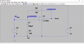
This shows the same basic circuit but now configured for a high AC gain. The capacitor blocks DC current.
Can you see how the same rule applies to the DC conditions ?
For the difference in voltage between the two inputs to be zero, we need 4 volts on the output.
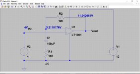
In the second picture I have made the cap leaky (4k resistance leaky) so that it draws current. The opamp wants to try and bring the voltage on pin 2 up to 4 volts and so maintain the 'zero volt differential' between the two inputs but it can not because of the limited supply voltage and the high value of feedback resistor.
This is similar to what you are seeing. The big question is whether the opamp is duff, or..........
Can you see how the same rule applies to the DC conditions ?
For the difference in voltage between the two inputs to be zero, we need 4 volts on the output.
In the second picture I have made the cap leaky (4k resistance leaky) so that it draws current. The opamp wants to try and bring the voltage on pin 2 up to 4 volts and so maintain the 'zero volt differential' between the two inputs but it can not because of the limited supply voltage and the high value of feedback resistor.
This is similar to what you are seeing. The big question is whether the opamp is duff, or..........
Attachments
Many thanks for taking the time to explain things. I will try to fully understand this over the next few days while waiting for the parts to arrive.
Just got the parts for the Helium micro monitor build, so might start planning that today and take off the jewellers loupe for a bit (that was giving me a headache).
Cheers
Just got the parts for the Helium micro monitor build, so might start planning that today and take off the jewellers loupe for a bit (that was giving me a headache).
Cheers
Hmmm
At least you have eliminated it as a possibility.
Yes, you need to look very carefully at what is connected to that input of the opamp and see if there is a problem. It sounds for all the world as if there is a lower than intended resistive path to ground on that input that is pulling that pin down.
Usually the opamp would be the last suspect and its far more likely to be a component fault around it.
At least you have eliminated it as a possibility.
Yes, you need to look very carefully at what is connected to that input of the opamp and see if there is a problem. It sounds for all the world as if there is a lower than intended resistive path to ground on that input that is pulling that pin down.
Hi Dunk,
Sorry to hear that replacing U3 did not bring you any further, and respect for the fact that you managed to replace two SOIC's.
However, going back to your previous #42 and #44 it is obvious that the problem seems to be around U3.
DC voltage on pin2 is completely out of range, and there is also no AC voltage entering this pin.
For this reason Pin1 produces no sensible output and therefore the other half of the Op Amp, receives no input signal.
Looking at the magnitude of the signals, 30 mV on pin 2 should result in 200mV on pin 1, a gain of 7x as can be seen on U2.
In #77 I have tried to find out what components are connected to pin 2 of U3.
So try to find out with a multimeter what the values are for R36, R27 and R29 with no power supply connected and also check the resistance from these points to GND.
Then connect the power supply and measure the DC voltage on both sides of these 3 resistors.
And this time use the correct GND connection as of Pin 4, which should be the same as the outer side of the 4 Cinch connectors.
Succes,
Hans
Molly, I think I grasp most of the info you kindly provided me. Printed out the circuits and followed along with your description - thanks again. I had to do some reading on RC networks while I was travelling for work, that was useful.
Hans, I have followed your instructions, and using U3 pin 4 as the ground I measured the following resistances and voltages. The results do not look the same as I previously posted. Also got myself some fine pointed leads for the DMM - that is making things easier,
Resis;Marked;Measured;Resistance to GND from each side;Vdc(r-gnd)
R27; 332; 3.3K; 960, 4.2k; 0.56, 0.14;
R29; 333; 33.2k; 37k, 4.2k; 4.8, 0.56;
R36; 331; 326k; 640,960k; 0.15, 0.01;
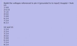
Redid the voltages referenced to pin 4 (grounded to to input) Vsupply= 9vdc
U3
1 4.8
2 0.15
3 1.6
4 0.0
5 4.8
6 2.4
7 2.4
8 2.3
U2 and U1
1 2.4
2 2.4
3 2.4
4 0.0
5 4.8
6 2.4
7 2.4
8 2.4
I also did some continuity checks and perhaps C24 and R29 are not in parallel in the feedback circuit, but in series, as determined with continuity checks either side of the capacitor.
The resistors aren’t be shorted.
C23 has continuity to ground on one side only when tested with the DMM so it has not shorted.
R15 is intact 47k
R25 is marked as 10k but measures 5k only in circuit.
Does this get us any further?
Cheers
Hans, I have followed your instructions, and using U3 pin 4 as the ground I measured the following resistances and voltages. The results do not look the same as I previously posted. Also got myself some fine pointed leads for the DMM - that is making things easier,
Resis;Marked;Measured;Resistance to GND from each side;Vdc(r-gnd)
R27; 332; 3.3K; 960, 4.2k; 0.56, 0.14;
R29; 333; 33.2k; 37k, 4.2k; 4.8, 0.56;
R36; 331; 326k; 640,960k; 0.15, 0.01;
Redid the voltages referenced to pin 4 (grounded to to input) Vsupply= 9vdc
U3
1 4.8
2 0.15
3 1.6
4 0.0
5 4.8
6 2.4
7 2.4
8 2.3
U2 and U1
1 2.4
2 2.4
3 2.4
4 0.0
5 4.8
6 2.4
7 2.4
8 2.4
I also did some continuity checks and perhaps C24 and R29 are not in parallel in the feedback circuit, but in series, as determined with continuity checks either side of the capacitor.
The resistors aren’t be shorted.
C23 has continuity to ground on one side only when tested with the DMM so it has not shorted.
R15 is intact 47k
R25 is marked as 10k but measures 5k only in circuit.
Does this get us any further?
Cheers
Those voltages aren't making much sense tbh.
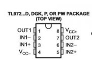
Lets start again with basics. If you place your meters black lead as shown here (marked reference), what voltage do you see on pin 8, marked in red ?
Also, are we in agreement that the opamps are of the same pinout as the TL972 ?
You should be seeing the full supply voltage between pin 4 and pin 8 if the opamps conform to that pinout.
Also, if you then measure any DC voltage between pin 4 and the outer ground part of the RCA sockets are you seeing zero volts ?
You should also (amp off now) read virtually zero ohms between pin 4 and the sockets.
Keeping your meter lead on that same pin 4, you should also see the supply voltage on pins 8 of the two remaining opamps U2 and U3.
Attachments
Sorry, typo. Measured 326 ohms.
The inability to correct errors in posts is a frustration I have with the way this forum works compared to some others. I think you only get 30 minutes to make any changes.
It is about 30 minutes, no more. Its done that way to prevent (mainly) historical changes being made to threads that could render following replies that had occurred misleading.
Think of a thread as a timeline with each reply building on the next
Hi Mooly,
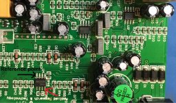
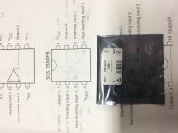
I have attached a picture to show the opamps I installed and the pin diagram I used today. I have been measuring the voltages as indicated referencing to pin 4. (Vdd in my schematic).
Between pin 4 and 8 on all opamps on the board V= 4.8V. I believe this is the correct supply voltage as the SN7805PI is a 5v regulator. Sorry, only mentioned 9V previously.
Pin 4 is connected to the RCA grounds, zero volts. Zero ohms - correct.
In my previous post the order of reading should have been
U3 ( the one under questions)
U2 and U4, not U2 and U1.
Attachments
Last edited:
OK So the supplies appear correct at 4.8 volts. That was the first thing to prove.
In your readings above you have pin 8 for all the chips as being around 2.4 volts and pin 5 as being 4.8 volts. So that means there is of course doubt over all the other results.
I think if you could repeat the readings for all 3 opamps keeping the black lead firmly on the point I marked above and then lets see where we are at.
Does that make sense
So the supplies appear correct at 4.8 volts. That was the first thing to prove.In your readings above you have pin 8 for all the chips as being around 2.4 volts and pin 5 as being 4.8 volts. So that means there is of course doubt over all the other results.
I think if you could repeat the readings for all 3 opamps keeping the black lead firmly on the point I marked above and then lets see where we are at.
Does that make sense
- Status
- This old topic is closed. If you want to reopen this topic, contact a moderator using the "Report Post" button.
- Home
- Source & Line
- Analogue Source
- Phono Pre-amp fault