Will go and ask GZ how that is done.
In my case, the record is fixed with a clamp, so if the hole is bigger I could just manually center, clamp it down, and try again - to be repeated a few times. Probably quite hard to get it right so that wow&flutter is at minimum. And, I am not sure if I can adjust to better than 0.2mm, if that is the spec from GZ...
Maybe somebody could come up with a clever device of , say, two eccentric plastic pieces that can be adjusted by turning or so, and we could 3D print them?
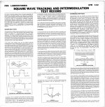
The purpose is to end up with triangular shaped grooves. The straight sections are constant stylus velocity, and good for analysing both trackability and tracing/generator linearity. The apexes are constant stylus acceleration, and good for analysing trackability/traceability as well as stylus profile performance as well as wear (in principle), and programme material slew rate performance.I looked at doing some triangle waveforms, then low passed them to 30kHz, applied RIAA and saved. With inverse RIAA (as applied at mastering/cutting) they were right back to triangles again - to be engraved on the master.
....(..)....
What will they tell us and how will we analyze them?
Magnetic cartridges are stylus velocity sensitive. So playback of a triangle shaped groove shape produces square wave cartridge output. Top/bottom flats represent constant stylus velocity part of the (angled) straight triangular groove shapes, and rise time represents stylus acceleration, the triangle apexes. So one can simply analyse playback cartridge output squarewave and assess performance of key cartridge and stylus parameters.
So test tracks with graded triangular angles and apex curvature in physical groove shape are needed. Not a triangle wave in the synthesised audio test file. The audio has to be synthesised depending on RIAA, where the track is on the record, and our graded choice of test parameters.
LD
") .
.
I found an interesting PDF from Aqvox (Germany; Phono Stage MFR) with regard to Lathe Cutter Head filters (high frequency). I don't know how accurate the information is, or whether it has any bearing on this project, but I suggest interested parties at least peruse it.
http://www.aqvox.de/download/Aqvox-RIAA-50kHz.pdf
http://www.aqvox.de/download/Aqvox-RIAA-50kHz.pdf
OK, does this mean that if inverse RIAA correction were turned off to the cutter head, a triangular waveform would not result in a triangular groove shape? What would the waveform be, in that case?So test tracks with graded triangular angles and apex curvature in physical groove shape are needed. Not a triangle wave in the synthesised audio test file. The audio has to be synthesised depending on RIAA, where the track is on the record, and our graded choice of test parameters.
Lots of clever ideas for mechanical devices that could correct an off center hole.I still like Scott's idea of a 45-sized hole and a gizmo that fits in there and allows the record to be centered.
But this being the 21st century and the era of fast math by computer - isn't there some way to correct the eccentricity by software? We know what the period is, and if the 3150Hz file has a marker that might even help. Since the period of eccentricity is so easy to know, can't we find it and null it?
Except the offset is not fixed.
Nope.
Yes, that is what Scott spoke about.
Normally I have these kinds of discussions with Scott.
My reading of your comments is that if we have a record with the center hole displaced on a cartesian coordinate system of .07 mm X axis and .07 mm Y axis that is not the same as .1 mm @ 45 degrees?
If we had a optical magic centering device and we moved the record on the Y axis until we were in the center of the grooves at the maximum X axis distance, that would not be the center of the record. We could even home in a bit more by then moving it on the X axis and aim for the center of the Y axis grooves. Again that would not be the center of the recording.
Pano, it would be possible to use software to correct for the frequency shift but that is not the only issue with an off center record. Part of getting a good centering is too see what else pops up as measurable.
I suspect if one were designing the center hole today it would have additional grooves radiating from the center to allow an oversize spindle to compress the softer vinyl without causing the warp to move outward.
OK, does this mean that if inverse RIAA correction were turned off to the cutter head, a triangular waveform would not result in a triangular groove shape? What would the waveform be, in that case?
AFAIK the SRT112 is cut without RIAA and the grooves are triangles I posted a microphoto here. You do not get squarewaves unless you use a flat preamp.
Ed - That's not fair I never mention anything but finding the angle and distance for correction. I said I saw someone that made a large hole and machined a device with two eccentric rings with a 33 RPM hole in the middle in such a way that rotating both rings inside the big hole could always center it exactly. Both rings were indexed (LP marked) so the position for each LP could be recorded.
If you look at one of our radial plots it's obvious that if the disk and platter were synced the exact amount and direction of correction can be read (computed) directly from the plot. Do you disagree that rotating an off center LP and moving it until the cartridge no longer moves side to side does not center the LP?
Last edited:
...
If we had a optical magic centering device and we moved the record on the Y axis until we were in the center of the grooves at the maximum X axis distance, that would not be the center of the record. We could even home in a bit more by then moving it on the X axis and aim for the center of the Y axis grooves. Again that would not be the center of the recording.
....
Today I asked GZ (the potential maker of the test LP) about their exact specification for the center hole, and also about the possibility to make one circular groove closed in itself, that could be used with a microscope to center the record, as Scott suggested.
I also asked them if they can master a disc without their RIAA involved, so we have full freedom over the signals we want to put. Obviously, that would mean we would have to apply RIAA (mathematically?) to the signals that need it.
So far no answers, will keep you posted
Last edited:
Ed - That's not fair I never mention anything but finding the angle and distance for correction. I said I saw someone that made a large hole and machined a device with two eccentric rings with a 33 RPM hole in the middle in such a way that rotating both rings inside the big hole could always center it exactly. Both rings were indexed (LP marked) so the position for each LP could be recorded.
If you look at one of our radial plots it's obvious that if the disk and platter were synced the exact amount and direction of correction can be read (computed) directly from the plot. Do you disagree that rotating an off center LP and moving it until the cartridge no longer moves side to side does not center the LP?
Scott,
Thanks for the laugh! We are in complete agreement on this. The issue was someone else's understanding of what I wrote. Not quite sure how you machine a pair of eccentric rings to accomplish the result. Much easier to make a sliding track with a scale and adjust distance and angle in my opinion. Again easy to calibrate if you figure text on the label is on the X axis.
Good question. Is dithering needed with 24 bit files? Or 32bit float?
With an LP dithering is moot, there are at least 6-8 LSB's (24 bit) of noise in the very best of cases so I would suggest we provide 24 bit files. The half RIAA does us no good I suspect the lower portion is insurance against gross bass excursions. The CBS non RIAA LP's all treat above and below 500Hz differently. For instance there can't be a 20 - 50k constant velocity sweep.
Last edited:
So test tracks with graded triangular angles and apex curvature in physical groove shape are needed. Not a triangle wave in the synthesised audio test file. The audio has to be synthesised depending on RIAA, where the track is on the record, and our graded choice of test parameters.
LD
There's nothing to prevent us from using linear phase filtering i.e. an ideal triangle with uniformly curved apex would produce a square wave with "s" shaped edges and gaussian shaped derivatives. The argument in the STR112 notes is based on a perfect triwave with abrupt discontinuities hence my confusion on how the G's come into it. This would be a tool that does not exist.
How would this be analyzed and used? What does it tell the end user?
The varying G forces tell a lot about tracking (I think) I'm sure the details are in Lucky's numerous early posts somewhere.
Well in that very post he already wrote that the waveform would be a rectangle.....in order to get a triangle groove.OK, does this mean that if inverse RIAA correction were turned off to the cutter head, a triangular waveform would not result in a triangular groove shape? What would the waveform be, in that case?
of couse, it has to be bandwith limited to ?? and passed through RIAA.
- Home
- Source & Line
- Analogue Source
- Test LP group buy