Hi Bryan
My suggestions are offered as I am aware you are measuring properties of the constructions that are being produced.
I am sure you have sealant/adhesives that are totally fit for purpose and your choice of a material that can offer a flexion when cured is showing this.
My additional suggestions are more leaning toward the idea that if one was trialled it might show a measurement that is seen as an improvement.
The Polysulphide Silicone is used in locations where movement of materials is expected to happen, so it will have a flexion.
The most flexion Silicone I know off is a Butyl Rubber based Silicone, it will have a bounce back/memory property when cured and pressure is applied to the surface.
are you saying the product is a mix of butyl rubber and silicone, or are you using the term 'silicone' in a generic sense? Do you have a trade name for it?
A Silicone Sealant is a generic term, the function of each Sealant will be determined by the environment the Sealant is to be used in.
The properties of each Silicone Sealant Type will be identified to be the best selection for the intended use.
The following links of Two Types will direct to a supplier within the UK.
Everflex 145 Butyl Sealant | Professional Sealants UK | Everbuild
Polysulphide Mastic Sealants Sealants Online
The properties of each Silicone Sealant Type will be identified to be the best selection for the intended use.
The following links of Two Types will direct to a supplier within the UK.
Everflex 145 Butyl Sealant | Professional Sealants UK | Everbuild
Polysulphide Mastic Sealants Sealants Online
A silicone is not a generic name, it is very specific. A compound or group of compounds which have a silicon atom replacing the carbon atom in organic chemicals. The butyl rubber suggested is not a silicone, whereas the polysulphide may be a mix of polysulphide and silanes, which are structural analogues of saturated hydrocarbons (alkanes).
I'm very concerned by the amount of noise in your results. What voltage are you running your accelerometer at?
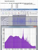
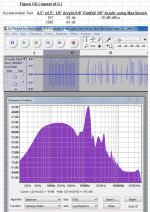
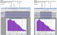
Here's repeat readings on the two extremes for the Accelerometer tests. This time, the Equalized waveform is shown on a linear scale.
Figure AA is a repeat of the earlier Figure A (Acrylic/MDF/Acrylic with stiff PL glue). Figure GG is a repeat of the Acrylic/Part Board/Acrylic with the softer MaxStretch caulking.
Attachments
I think I can safely say that the Phono cartridge results (Figures B,D,F,H from one page back) are not so relevant. I added a metal knob to the mimic plinth as a mimic platter and things changed quite a bit. If I come up with something that seems meaningful, I'll post it.
Hugh
Hugh
The following links of Two Types will direct to a supplier within the UK.
Everflex 145 Butyl Sealant | Professional Sealants UK | Everbuild
Polysulphide Mastic Sealants Sealants Online
John,
That site has a very good variety of sealants. Would those brands be the same ones you'd find in retail stores in the UK? If not, what are the popular retail brands?
Hugh
Here's repeat readings on the two extremes for the Accelerometer tests. This time, the Equalized waveform is shown on a linear scale.
Figure AA is a repeat of the earlier Figure A (Acrylic/MDF/Acrylic with stiff PL glue). Figure GG is a repeat of the Acrylic/Part Board/Acrylic with the softer MaxStretch caulking.
looks better, but try to get about eight 'hits' with the hammer, and discard (erase) any suspect ones, which are not 'perfect' waveforms. Then use the ones which are left for the FFT.


At this stage, I'm trying to figure out which adhesive to use on the full sized plinth. Hard glue similar to PL? Soft elastic one like GE Maxstretch?
The earlier screenshots suggested that maybe the elastic one will snuff out those vibrations in the 500 to 2000 hz range. But what actually gets to the cartridge?
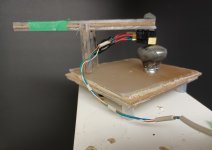
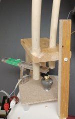
Figure K is a cheap attempt to find out. Please don't laugh too hard.
The 4.5"x4.5" panel has 3 plastic feet - two at the front and one centered in the back. This is similar to a Rega P6 for foot locations.
The metal knob (covered with Ductseal) is supposed to represent the mass of a hub and platter. It's 1" off the centerline to mimic a Turntable.
The "Tonearm" is mounted at the back to one corner. Please ignore the fact that it's backwards.
The earlier screenshots suggested that maybe the elastic one will snuff out those vibrations in the 500 to 2000 hz range. But what actually gets to the cartridge?
Figure K is a cheap attempt to find out. Please don't laugh too hard.
The 4.5"x4.5" panel has 3 plastic feet - two at the front and one centered in the back. This is similar to a Rega P6 for foot locations.
The metal knob (covered with Ductseal) is supposed to represent the mass of a hub and platter. It's 1" off the centerline to mimic a Turntable.
The "Tonearm" is mounted at the back to one corner. Please ignore the fact that it's backwards.
I did edit out some slightly rogue pulses in the following figures. It did make some subtle changes to the FFT waveforms.
Figure L is what the cartridge picks up when I tap the middle of the panel. In this case, it's the Maxstretch and Particle board version. I'm suggesting this would represent the response to external noise, motor vibration, etc. Note how the lower frequencies look pretty lumpy.
Figure M is the same Maxstretch panel when the knob is hit. I'm thinking this reperesents vaibration from the record surface, down the through the platter and hub and reflected back to the cartridge. (Of course an actual platter would contribute other resonances.)
This too is a little lumpy is the bass. The width of the pulses suggests the damping may be OK (I didn't calculate any DFs just yet.) Resonances above 500 are also present, but lower in amplitude by 20 db and more.
Figure N uses the Stiffer PL adhesive. When the panel is tapped in the middle, there's a less lumpy response in the bass. Content above 500 hz is fairly well behaved.
In figure O, the PL adhesive panel is tapped on the knob. The bass response looks better than figure M to me. Resonances above 500 hz are present. The peaks look similar in width to figure M suggesting similar damping. But, they are just a bit higher in amplitude.
It appears there's some tradeoffs here. The elastic adhesive seems to loose a bit of control in the bass, but helps just a bit above 500 hz. This seems to agree with Cats Squirrel's misgivings with CLD. True?
I was leaning to the Elastic adhesive for my full size plinth. Now I'm thinking something stiffer would be better. I may pick one that I can pull apart in case of more surprises, so PL will not be the one.
Hugh
Attachments
Sorry guys, I'm flip-flopping now.
I tried repeating the results from those earlier tests and found the PL one behaves well when it's hit unrealistically hard, but poorly to a softer tap. So I'm back to the Maxstretch one as my favorite. It seemed more uniform for light and hard taps.
I also tried a piece of 4.5"x4.5" x1/4" mdf as a miniature plinth just for some perspective. I'll post that later.
More on Adhesives
I wanted something more repeatable than hammer taps for comparing materials, especially the adhesives. Good or bad, I decided to use an 8mm plastic craft bead dropped down a one foot pipe as my hammer substitute. Figure P reveals that it does not produce the same FFT spectrum as the hammer, but still useful I hope.
Don't take these results as the last word. The bead taps were not as consistent as I wanted. I'm sure a full sized Turntable will behave differently than these mocked up models.
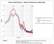
In Figure Q , the cartridge sits on top of a metal knob that's attached to a 4.5" square mock up of a Turntable. It's about 1/4 scale. The bead is dropped near the center of the Miniature Plinth and the cartridge output recorded through a Phono input on an old DJ mixer.
The Purple trace is a piece of 1/4" x 4.5"x4.5" MDF as the plinth. The other two traces are 2 layers of 1/8" Acrylic with a 1/8" layer of MDF as a core. The Blue trace uses Maxstretch (a soft elastic caulking). The Grey trace uses Lepages PL which is a Polyurethane adhesive that sets up fairly hard.
The MDF produces lots of sharp, poorly damped peaks at 300 hz and up.
Maxstretch (Blue) appears to smooth out those nasty 300 hz + peaks. But there's a cost - it produces 2 more peaks from 50 to 200 hz. I'm guessing this will ampilfy motor and bearing vibration by a few dB.
The PL (Grey) is good in the low frequencies up to about 800 hz. Then it gets a little ugly between 1000 and 2000 hz.
I also tried a mock up using Greenglue between the layers. It had even more pronounced lumps in the bass region. So, I think I see why Cats Squirrel is not keen about CLD in a plinth.
For external vibration, I think a hard glue like PL is my preference. Low frequencies like motor and bearing noise are kept to a minimum. What would excite the higher frequency peaks? Airborne sound? I'm thinking the record surface would pick up more of that than the plinth.
(Please post something if you have any insights that say otherwise.)
Hugh
I wanted something more repeatable than hammer taps for comparing materials, especially the adhesives. Good or bad, I decided to use an 8mm plastic craft bead dropped down a one foot pipe as my hammer substitute. Figure P reveals that it does not produce the same FFT spectrum as the hammer, but still useful I hope.
Don't take these results as the last word. The bead taps were not as consistent as I wanted. I'm sure a full sized Turntable will behave differently than these mocked up models.
In Figure Q , the cartridge sits on top of a metal knob that's attached to a 4.5" square mock up of a Turntable. It's about 1/4 scale. The bead is dropped near the center of the Miniature Plinth and the cartridge output recorded through a Phono input on an old DJ mixer.
The Purple trace is a piece of 1/4" x 4.5"x4.5" MDF as the plinth. The other two traces are 2 layers of 1/8" Acrylic with a 1/8" layer of MDF as a core. The Blue trace uses Maxstretch (a soft elastic caulking). The Grey trace uses Lepages PL which is a Polyurethane adhesive that sets up fairly hard.
The MDF produces lots of sharp, poorly damped peaks at 300 hz and up.
Maxstretch (Blue) appears to smooth out those nasty 300 hz + peaks. But there's a cost - it produces 2 more peaks from 50 to 200 hz. I'm guessing this will ampilfy motor and bearing vibration by a few dB.
The PL (Grey) is good in the low frequencies up to about 800 hz. Then it gets a little ugly between 1000 and 2000 hz.
I also tried a mock up using Greenglue between the layers. It had even more pronounced lumps in the bass region. So, I think I see why Cats Squirrel is not keen about CLD in a plinth.
For external vibration, I think a hard glue like PL is my preference. Low frequencies like motor and bearing noise are kept to a minimum. What would excite the higher frequency peaks? Airborne sound? I'm thinking the record surface would pick up more of that than the plinth.
(Please post something if you have any insights that say otherwise.)
Hugh
Attachments
MDF or Chipboard?
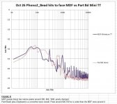
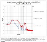
There was discussion earlier about MDF vs Chipboard (aka Particle Board over here). Figure R compares them as 4.5" x4.5" x 1/4" Miniature plinths.
Figure S shows how MDF and Particle board compare as 1/8" Cores with 1/8" Acrylic outer layers. PL adhesive holds them together.
All of the above were bead taps near the plinth center, simulating (I hope) vibration from outside (e.g footfalls, motor and bearing vibration,etc).
Attachments
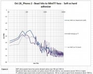
Vibration from the record surface
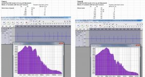
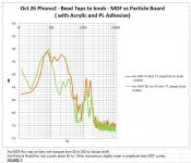
Figure T is taps to the knob. This attempts to simulate vibration starting at the stylus and echoed back from the plinth. The 2 traces are 1/8" Acrylic outer layers. The orange trace is a 1/8" mdf core with PL glue. The green trace is a 1/8" Particleboard core with PL glue.
Overall, the Particle board core looks to produce lower levels, except for that one peak around 80 hz. The narrow bandwidth suggests poorer damping. Tougher choice on this one.
H
Attachments
Lots of things to discuss, I'm afraid Hugh.
I'm not sure that what you are now doing is of much use. Going away from a tried and tested (and industry standard) method of testing for vibrations in small objects is not a good thing. The use of the recommended hammer has proved very successful for me over the years. With a bit of practice, one should be able to hit the test piece with a very short contact time, thereby invoking a broad band spectrum of major modes. The accelerometer is the transducer of choice for vibration testing of small objects. Your recent use of a moving magnet cartridge is not, in my opinion, a good thing. It shows vibrations in two directions at once, confusing the issue. And placing the test apparatus on the test piece is a no-no. The test piece must be suspended. All this will then provide data from which objective conclusions can be made.
Looking at what you have shown, only the mdf and particle board on their own make any sense. The mdf trace shows many more peaks, as would be expected from its low damping figures. But not from the mdf, I think, but from the brass knob. The fundamental is at 300 Hz, 2nd harmonic at 600Hz, 4th at 1200 Hz, and pro rata.
Hope that helps.
- Home
- Source & Line
- Analogue Source
- DIY CLD Plinth Design--A measured Approach