why do these test always involve hitting the sample with a hammer?
nothing like this goes on during record playback,wouldn't the results be more 'real world' if a sample piece was attached to the plinth and then measurements taken from it whilst playing a test record?
Hi jamie123,
Not quite what you're asking but...
I did record the cartridge output on a Rega TT while tapping the shelf, plinth and the LP surface in a few places. I think it will interest some. Haven't made the time to post it yet.
Hugh
Can you explain how?
the idea is to transfer as much energy (vibrations) from the arm to a damping material, one that is stiff enough to support the arm without bending. ALL (!) one has to do is match the mechanical impedance of the arm (mount) and arm board. The maths is not that complicated.
Mechanical impedance = n x SQRT(ρ x h x B)
where n is just a number (see later)
ρ is density (of arm mount) or arm board. in kg/m³
h is thickness of arm base or arm board (see later) in metres
B is bending stiffness
B = YM x h³ / 12 ( 1 - v²)
where YM is the Young's Modulus or arm base or arm board) in GPa
h is thickness (in metres) as above
v is Poisson's ratio of each
n is a number which depends on where on a panel the arm is mounted. Take it as 8 if in the middle of the arm board, or 4 if towards one end. YM is tabled in the literature for most materials. Poisson ratio, if not known, should be about 0.3, but it won't make much difference, although it has to be between 0.0 and 0.5
Then ALL you have to do is match the two materials. Note, what is not transmitted is reflected (ignoring radiation). So for reflection,
MI of arm base = a
MI of arm board = b
then reflection = (a-b)/(a+b) x 100%. If the answer is a negative number, just reverse a and b.
Transmission is just 100 - above. Hope that is clear.
I hope that it can now be seen that to match the impedances (so as to obtain near maximum transmission of vibrations), one can change the thickness of the arm board. One reason why no one arm board fits all arms!

However, transmission is two way, so the arm board has to have a lot of damping, or if there is little transmission, the arm will have to cope with the reflected vibrations.
HTH
Last edited:
why do these test always involve hitting the sample with a hammer?
nothing like this goes on during record playback,wouldn't the results be more 'real world' if a sample piece was attached to the plinth and then measurements taken from it whilst playing a test record?
as noted by Mickey above, it allows broad band measurements of the resonances (modes) of a test piece. The rationale for this is to test materials for suitability in plinth, supports and loudspeakers box walls.
The idea is to hit the test object with a very short duration pulse, so as to excite all the modes of interest. Once tested, and suitable materials determined, it is then possible to construct a plinth/support/LS box with confidence in the results. The alternative is to 'suck it and see', which usually ends up with lots of failed projects, or inferior product.
To carry out the test, one uses an accelerometer which is rigidly attached to the test piece, and the latter hit with a SMALL hammer with appropriate head. Often the hammer is fitted with a force transducer, I never do. The output from the accelerometer is fed to a computer, so record the waveform, and allow filtering, ultimately to determine the damping factor of the test piece.

Here is a typical trace, this is ebony, much loved by head shell makers, why? 'cause it looks nice... Note the exponential decay.
Last edited:
the idea is to transfer as much energy (vibrations) from the arm to a damping material, one that is stiff enough to support the arm without bending. ALL (!) one has to do is match the mechanical impedance of the arm (mount) and arm board. The maths is not that complicated.
HTH
Wow, thanks a lot. Really appreciate your effort here. I will have to consider this before any work now… i have some nice pieces of black aluminum 1-2mm thick I had in mind for this. I will have to plan it wisely. Maybe add some layer of another material to it… or go for some other material.
Wow, thanks a lot. Really appreciate your effort here. I will have to consider this before any work now… i have some nice pieces of black aluminum 1-2mm thick I had in mind for this. I will have to plan it wisely. Maybe add some layer of another material to it… or go for some other material.
That's why i am reading it and learning as well Misko, i use Avonite (Corian like and i have lots) for my LTA mount and plinth at the moment, its without doubt better than the MDF i used before but is it best?
M
Although Corian ® was flavour of the month with audiophiles, and although it has 2 to 3 times the damping of mdf, it is still very low (DF 0.044), and not fit for purpose, a bit like slate, another flavour of the month (DF 0.017)
This figure was for Corian ® and other similar products may be different.
This figure was for Corian ® and other similar products may be different.
Although Corian ® was flavour of the month with audiophiles, and although it has 2 to 3 times the damping of mdf, it is still very low (DF 0.044), and not fit for purpose, a bit like slate, another flavour of the month (DF 0.017)
This figure was for Corian ® and other similar products may be different.
Many thanks for that feedback, do i remember that you tabulated some starting points for impecunious builders? - value high DF mats to look at please?
Thanks
@cats squirrel
I think I have read you are using RB250 with L75. What is your choice for armboard in that case?
@Cats
On top of this question, I have one more for you, sorry if I am boring...
What should be considered as "arm base" for Rega RB 250 in order to do the calculations? This black bottom "ring" before brass part? Brass mounting? Nut? Not sure what to take into calculations...

Cats,
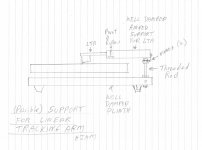
I have a similar question. I'm attaching a sketch of what I intend for supporting my next Linear Tracking Arm. I'm assuming the threaded rod (steel or brass) will be an impedance mismatch for an Acrylic or Panzerholz plinth. True?
Is there any point in trying Nylon or other plastics, or does the rod shape pretty much dictate that it will be an impedance mismatch?
H
Attachments
OK, back on planet Earth!
The calculation for mechanical impedance is correct, although as one person has pointed out (private comms) that one needs to include the 1 billion multiplier to convert GPa to just Pa.
therefore: MI = 8 * SQRT ( density * h * D)
where density is in kg/m³
h is in metres
D = (YM * h³/ 12 (1 - v²)
where YM is Young's modulus in Pa
v = Poisson ratio
So that, D = (YM (in GPa) * 1000000000 * h³ (in metres) ) /12 (1 - v²)
For the Rega arm, I have assumed the base is made of brass, and is 20mm long, which has a mechanical impedance of around 30,000.
Materials and thicknesses which have virtually the same MI are:
acrylic (80mm)
ply (90mm)
Panzerholz (50mm)
ipe wood (50mm)
one can see that the arm board needs to be quite thick, and that arm towers would be more suitable, unless one has a 90mm thick ply plinth (they do exist) but unfortunately ply has little damping. Thick plinths have many other problems, too.
I hope that this has been useful. It should now be apparent that arm 'boards' need to be thick (although not large), and that one board cannot fit all arms!
Just a word of caution, don't try to chase numbers, 80%+ would be sensible, and MUCH better than the vast majority of arm boards out there. The elephant in the room, as always, is material damping. Start from there.
that is what I used. It is a difficult choice, none of which is wholly satisfactory.sorry but it is not clear to me what you mean by "base" of the rega tonearm. The lower and upper ring that tightens the tonearm on the armboard?
It is a difficult choice, none of which is wholly satisfactory. I used the the bit between the bearing and the thread. About 20mm in length, I believe.
btw, I’ve made something for the New Year
as i have said, acrylic-chipboard-acrylic, pretty simple… 10mm/12mm/10mm. glued in sandwich with mentioned 3m tape.


used your suggestion for position of spikes , which bases are decoupled from shelf with some shoe dampers

you can see how i tried to isolate the arm. just drilled till chipboard, so its like its on some kind of island... just one 3mm aluminum plate also glued between top acrylic island and base of the arm, for height leveling purpose... sounds great, i am very satisfied. Could look way better i know, but didnt have time for better shiny looks this time...
as i have said, acrylic-chipboard-acrylic, pretty simple… 10mm/12mm/10mm. glued in sandwich with mentioned 3m tape.
used your suggestion for position of spikes , which bases are decoupled from shelf with some shoe dampers
you can see how i tried to isolate the arm. just drilled till chipboard, so its like its on some kind of island... just one 3mm aluminum plate also glued between top acrylic island and base of the arm, for height leveling purpose... sounds great, i am very satisfied. Could look way better i know, but didnt have time for better shiny looks this time...
Last edited:
- Home
- Source & Line
- Analogue Source
- DIY CLD Plinth Design--A measured Approach