Hello Byran and thanks for joining the conversation (cats squirrel is the author of the sites I referenced in the OP).
I appreciate your insights to the materials and measurements. Question: How are you measuring or determining DF? I thought the Corian measured fairly well in the waterfall graphs (low amplitude and short duration)?
I should point out that my goal was not to produce the "ultimate" in plinth design (my background is in electronics). I sought only to improve on the current design (thick MDF tightly bonded to a steel plate), and to start a conversation about design techniques that rely on measurements and science. Your work in this area is greatly appreciated and I hope you can continue to provide valuable insight.
Last edited:
recent measurements - audio qualia
please let me know if the pics don't show. I moved (or was moved!) from photocrapet to Flickr and the pics suddenly appeared. Don't know what happened, long may it last.
I measure the damping factor by attaching my accelerometer to the test piece, edgewise, with masking tape, then suspend the test piece on thin thread. I use a small hammer (it has two heads, one made of steel, the other acrylic) and hit the test piece near the middle of it. I record the waveform using Audacity software, as I run a Linux variant OS. After recording, I apply equalising, as the accelerometer has low pass filters built onto its breakout pcb. [Note to Pyramid, to you compensate for this?]
Once the waveform has been recorded, I look at the amplitude decay. Sometimes the waveform is very clean, and two adjacent peaks can be chosen and noted. I do this on six samples. The damping factor can then be calculated from the log decrement. I also use a sanity check sum.
If the waveform is complex, like the Corian, I usually filter it using the Audacity functions, and proceed as above. I hope this is helpful.
Last edited:
Hello Pyramid,
Great work so far. I have been working on different plinth materials as well. I don't have an accelerometer at this time but use an electronic stethoscope for noise levels. One material that I'm looking at I didn't see on the list of materials is Richlite. It machines similar to the corian and polishes up nicely. Only commercial table I know of that uses it is Fern & Roby.
eco friendly paper-based fiber composite countertops, surfaces and materials | Richlite - Richlite
Last edited:
recent measurements - audio qualia
please let me know if the pics don't show. I moved (or was moved!) from photocrapet to Flickr and the pics suddenly appeared. Don't know what happened, long may it last.
I measure the damping factor by attaching my accelerometer to the test piece, edgewise, with masking tape, then suspend the test piece on thin thread. I use a small hammer (it has two heads, one made of steel, the other acrylic) and hit the test piece near the middle of it. I record the waveform using Audacity software, as I run a Linux variant OS. After recording, I apply equalising, as the accelerometer has low pass filters built onto its breakout pcb. [Note to Pyramid, to you compensate for this?]
Once the waveform has been recorded, I look at the amplitude decay. Sometimes the waveform is very clean, and two adjacent peaks can be chosen and noted. I do this on six samples. The damping factor can then be calculated from the log decrement. I also use a sanity check sum.
If the waveform is complex, like the Corian, I usually filter it using the Audacity functions, and proceed as above. I hope this is helpful.
Thanks for the link! The pics show up just fine.
Yes, I noticed the HF roll off in accelerometer response. They have caps on the output pins with a cutoff of ~750Hz IIRC. I changed them out to 1N0 caps and I believe the response is flat to >2kHz.
@Bon- Panzerholz is very expensive and difficult to source (especially in the US), although it would most likely have worked better than MDF. Corian is similar to Polyester/bentonite in construction (acrylic polymer and alumina trihydrate crystals) and it certainly measured the best of the 4 materials; I didn't see data on the audioqualia site for it? It would have been interesting to build a laminate structure out of Corian and Panzerholz.
@Ben & Bon- I've seen CLD described as a single rigid layer bonded to a single damping layer, and I've also seen the term applied to rigid-damp-rigid structures; perhaps there is a more accurate name for the latter?
I think the principal is the same however: A structure that damps vibrations through flexing and dissipates the energy as heat in the damping layer.
Thanks to everyone for the positive comments.
Hi Pyramid, (here come a long one)
Thanks for all your efforts with scientific measurements supporting your design of a turntable using Corian for the building material. I went through a similar process some 25 (or so) years ago without the benefits of the instrumentation. All I had was ears and hammers and tappings etc and came up with my design. For a picture please go to www.apricot.com/~bgruhn/turntable/77.jpg. I am still using that TT but have made a few changes. For one thing the WellTempered arm has been replaced with a linear tracking arm. You will note on the picture that there is an upper and a lower Corian plate separated front and rear by a seperate 3/4" square piece of corian. There are a total of 8 viscoelastic shock mounts mounted 4 on front corian separator and 4 on rear separator. These shockmounts were chosen because they were working well on hard drive applications my firm was making. They served well for the TT but I was not thrilled by their performance. After many years they were deteriorating. It was time to come up with something better. What I had learned in the interim was that CLD could very well be that something. I had some leftover snow & ice shield material from a roofing job. It was the thicker type with sticky black adhesive coating on one side. This I cut into inch wide strips and applied it to the separator pieces essentially gluing the top plinth and bottom plinth together. The result was nothing short of amazing. Tapping on the edge of the playing record gives only a barely audible dull sound that dies out instantly. I can do a similar tap test on the under side of the linear tracker's rails with the same result. My original TT motor was mounted on the bottom plinth plate and I was getting a lot of motor noise in the cartridge output. The new motor is mounted outboard and no more noise. One more thing worth mentioning is the shelf the TT sits on. even with the modified CLD TT plinth if I beat hard enough on the underside of the shelf I could get some action. Had an unused shelf which I placed on top of the exisfing one with a layer of sno&ice shield between them. Brother it is dead now.
So Pyramid thanks again for putting some science behind my doings and validating my actions. I couldn't be happier with the results. I am sure you will observe similar results. BTW your workmanship is beautiful beyond words.
BillG
Last edited:
bgruhn-
Thanks for the feedback and the kind words. I've had a chance to listen to the table for about a week now and have some observations:
To start with, this table replaced a VPI Scout with 9 inch metal unipivot arm. I was never a fan of the unipivot, and the queuing mechanism never worked right (the arm dropped like a rock). I replaced the JMW9 arm with a 10" Jelco SA-750E (Thanks to Jam for sending me this great arm!), so besides the queuing working correctly, the distortion has also decreased. This is readily noticeable on complex passages and louder program material, especially with higher frequency components. There also seems to be less sibilance. I also replaced the motor with a 3 phase BLDC version with custom drive and 3 belts, so the only thing left from the VPI table (for now) is the platter and bearing, which I hope to replace with a DIY SS/Delrin version sometime in the future.
I've noticed some rather profound changes in the sound, all of them good. I'm not entirely sure which ones are attributable to the different tone arm and which are the result of the plinth design (or the two working together). The changes are not noticeable all the time, just under certain trying conditions. If a play an LP that I am very familiar with, everything will sound nearly the same until some heretofore subtle detail suddenly stands out as clearer, less muddled. It is like a layer of haze has been removed and it is most noticeable on complex passages where leading edge focus has improved dramatically.
I've also noticed a tightening and clarity in the mid and lower bass tracks. On Paul Simon's Graceland LP, especially the tracks "Diamonds on the soles of her shoes" and "You can call me Al", I can hear the bass player's fingers as he pulls the stings of his guitar. Fleetwood Mac never sounded so lush and enjoyable before, especially the bass and Christine McVie's voice on "Warm Ways".
One thing I have noticed and can attribute to the plinth, is something you mentioned: With the stylus lowered onto a stationary record and tapping the plinth or the shelf, the sound generated is a dull, low frequency thud that ends as quickly as it starts, where before, there was a definite Pingggg.... at around 600 Hz with a long sustain. The shelf thud isn't as reduced as I would have thought or hoped, but it is significantly less than tapping on the plinth directly. The former 600Hz resonance was sometimes audible, not as direct feedback, but almost a faint echo or ghost and sometimes a harshness on certain tracks that would excite it. It is complete absent now.
Hi Pyramid,
glad to see that you are happier with the sound, although you have changed (nearly) everything, so it's to be expected. In the UK, we would call it a 'Trigger's brush' > YouTube
Ascribing improvements to different parts of the turntable would be difficult, sometimes they work together for the better, often they do not!! But improvements you describe could be put down to the plinth, although I think you could improve that further.")
Resonances don't happen at one frequency, but a whole lot of related frequencies, so instead of a single tone, one gets a chord, not necessarily a sonorous one!
glad to see that you are happier with the sound, although you have changed (nearly) everything, so it's to be expected. In the UK, we would call it a 'Trigger's brush' > YouTube
Ascribing improvements to different parts of the turntable would be difficult, sometimes they work together for the better, often they do not!! But improvements you describe could be put down to the plinth, although I think you could improve that further.
Resonances don't happen at one frequency, but a whole lot of related frequencies, so instead of a single tone, one gets a chord, not necessarily a sonorous one!
Funny YouTube video; point well taken. I've seen this on the Lenco Heaven website as well, where the only original component remaining after a rebuild is the motor (although arguably, one of the most important and surely uniquely Lenco parts).
Care to elaborate?
But improvements you describe could be put down to the plinth, although I think you could improve that further.
Care to elaborate?
Funny YouTube video; point well taken. I've seen this on the Lenco Heaven website as well, where the only original component remaining after a rebuild is the motor (although arguably, one of the most important and surely uniquely Lenco parts).
I must admit to being a bit guilty there, myself. The Lenco's are great if you use them as donor parts. I have bits to make six or seven Lenco tt, but I have only one (the oldest) that I have kept mostly stock, with added plinth bases and supports, and a better lift lower on the arm. New head shells too!
only to say that IMHO, it is better to start with materials that have good intrinsic damping, rather than choose materials for other reasons, and try to apply remedial damping.Care to elaborate?
In my (imaginary) book, plinths need to be thin and made of appropriate materials. They need some bending stiffness, but not too much, and have a little mass, but, again, not too much. And high damping factors are mandatory, as it impinges on the whole structure. Fundamental frequency needs to be low, and critical frequency high. Apart from that, you can do what you like!
All the many parameters need to be considered very carefully, as each will have an effect on all the others. It is a fine balancing act. Good luck
I'm not sure if I'm thrilled or distraught that this subject appeared and I came upon it.
I am in the throws of "bastardizing" my old VPI HW19 turntable in more ways than one. I romanced modifying it for years, and collected parts to that end. Bill's incredible work on the BLDC motor project is ultimately what got me off my procrastinating butt.
I also had come across the Dahlia page more than once a few years back. Unfortunately, I couldn't make complete sense of it and determine how to apply the information to a turntable project. I hadn't seen the more extensive list of materials evaluated for their damping factors posted at that point.
I had found a few other web pages related to commercial sound deadening materials that supposedly utilized CLD technology, but I was still left wondering what the heck constituted a visco-elastic material? How could I get my hands on it and use it with appropriately damped materials to make a better plinth? Did the materials need to be bonded together? Could they be held together mechanically with hardware? What was CLD doing in a plinth application? Was it isolating? Damping? Both? etc.
With my current project I decided that instead of building a fantasy table from the ground up a la VPI "Avenger" or the like with an exotic plinth that I would try to sustain the traditional format of the HW19 and try to optimize it as best I could.
I have slowly worked my way through the HW19. It is a MK2 version, which came with a steel/MDF plinth suspended via coil springs in the outer frame.
Common practice is to lose the coil springs and replace them with solid rubber electric motor style mounts. This supposedly results in better bass response.
The later HW19 models used acrylic attached to steel for the plinth. This modification has been performed many times on earlier models and it seemed like a no-brainer to try replacing the MDF with acrylic as I had come into a piece of 3/4" thick clear acrylic in the form of an old retail store display for free.
I was limited to mimicking the original layout of the table using a separate arm board as my usable pieces of acrylic were limited in size.
I am at a point now where the acrylic bearing support section of the plinth is complete and mountable to the lower steel layer.
I am reflecting on the Dahlia web page, specifically the section commenting on utilizing materials with very different impedance characteristics in order to limit the transfer of energy from one material to another.
I was thinking I should feel pretty good about the difference in these impedance characteristics between steel and the acrylic. I was hoping that at the very least this difference might help impeded the transfer of vibration/energy from the suspension/frame/shelf etc. up into the acrylic where the bearing/platter and tonearm are mounted?
I also wonder if the fact that I have to mount the tonearm on a separate acrylic arm board if it might benefit by being isolated from some vibration the bearing might be transferring directly through the acrylic if it was one piece? After all, acrylic doesn't have an amazing damping factor.
Bill mentioned how his goal was to isolate his upper layer and at the same time anchor (my word) the tonearm and platter to each other on that same plain. I have read about this in the past, specifically Harry Wesfield's opinion that it is desirable.
The most important question I would like to answer right now is what the heck should I put between the steel and acrylic on my plinth? They are two rigid layers, but they aren't identical or thin and so should not be viewed as a CLD application as far as I understand it, correct?
What should my goal between the steel and acrylic be? Perhaps there should be nothing in between? My layman's gut response is to insert some kind of thin damping material.
I am intending to hold the steel/acrylic layers of the plinth together with the original method of screws clamping them together from the bottom. I have added a few more to get a more even clamping between the layers around the bearing area. I am using bigger stainless hardware instead of the original wood screws. I have threaded the acrylic to receive the hardware.
If I use something, I'd prefer that it didn't bond directly to the other components of the plinth so that it was possible to try different materials. However, I don't know if it would be better to have a bonding laminate in between the steel and acrylic or not.
I considered simply using a layer of decent weight paper, but also considered impreganating it with rubberized paint or creating a sandwich of two pieces of paper with a layer of rubber applied between. The only thing that VPI applied between the original MDF and steel was a splatter of some kind of bonding agent, perhaps contact cement.
 VPI HW19
 if I understand you, you are talking about this?
They have replaced the 1" thick mdf top plate with acrylic/steel?
And you want to do something similar?
People (like me) who have Lenco's will appreciate (or not) most of that construction, but without the acrylic layer, and, of course, the motor is completely different. As you point out, the springs are the first to go, although I have kept the ones in my GL59/70, as they are man enough for the job, and don't need the foam inserts 'to control random motion'
.First point: if one isolates a structure (like the top plate) then it will vibrate without being influenced by other structures, as it is isolated. This means that unless one takes special care of the damping of the isolated structure, one can make matters worse!
Second point: adding many (or a few) materials together will not (necessarily) get you to a better place. There is a lot of folklore about different materials, reflections, cancelling resonances, and the like.
Most of this is true if we talk about supersonic frequencies, but the rest is fantasy. Generally, two or more materials, tightly bonded together will make a new material, which will have a different set of characteristics from the original individual materials. And in general, they will be roughly the mean of the individual material's properties, considering the respective thickness of each, although, because of the bonding, damping may improve.
Third point: cld comprises a thin vibrating panel, separated from another similar panel by a viscoelastic (ve) material. One that has both viscous and elastic properties when being deformed. Think sorbothane or 'Green Glue'. The important thing here is the word 'thin'. Cld cannot work if the structure is thick and cannot bend, so all those thick plinths which are called cld, aren't.
Ironically, if VPI kept the mdf (maybe 12mm thick) and bonded the acrylic to that, they would have ended up with a very reasonable new material, with a measured damping factor of 0.315!
Fourth point: the spacial integrity between the main bearing/platter/record and arm/cart/stylus MUST be maintained at all costs, this means NO compliant material be used in the structures these are mounted on.
As regards the question of what to put between the steel and the acrylic layers? I suggest the strongest glue you can find, then apply damping to the underside of the steel, because I think you will need it, lots of it.
Hope this helps.
You might look at the OP of this thread regarding Fr and Fc, and how it relates to material choices and thickness.
Also, this document goes a long way to explain damping techniques:
https://earglobal.com/media/9891/understandingdampingtechniques.pdf
Also, this document goes a long way to explain damping techniques:
https://earglobal.com/media/9891/understandingdampingtechniques.pdf
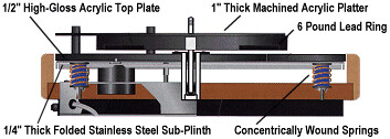
No...my earlier HW19 version in stock form is assembled the same as the picture. There was not just a 1" MDF plinth. However, the 1/2" of acrylic labeled in your diagram was originally 1/2" of MDF on my plinth. The 1/4" of stainless steel in your diagram is essentially the same structure in my table, but mine is made up of two 1/8" layers of steel. One fits inside the folded edges of the other and is tack welded underneath at the corners.
And you want to do something similar?
That sort of depends. Acrylic does have a slightly better damping factor than MDF according to your research.
First point: if one isolates a structure (like the top plate) then it will vibrate without being influenced by other structures, as it is isolated. This means that unless one takes special care of the damping of the isolated structure, one can make matters worse!
So a material with the best possible damping factor used for that upper layer would be ideal. In my situation, at least the proposed acrylic appears to be a better choice than MDF. The acrylic I have is also 1/4" thicker.
Second point: adding many (or a few) materials together will not (necessarily) get you to a better place. There is a lot of folklore about different materials, reflections, cancelling resonances, and the like.
Of course this is what I am trying to avoid.
Third point: cld comprises a thin vibrating panel, separated from another similar panel by a viscoelastic (ve) material. One that has both viscous and elastic properties when being deformed. Think sorbothane or 'Green Glue'. The important thing here is the word 'thin'. Cld cannot work if the structure is thick and cannot bend, so all those thick plinths which are called cld, aren't.
That seems pretty clear given the original design of my plinth and many others. I know the intended original topic in the thread was the idea of implementing CLD in the design of plinths. I hope I'm not derailing the thread by talking about laminates and achieving better damping through the use of them. Perhaps the discussion will help clarify things better with the examples of both?
Ironically, if VPI kept the mdf (maybe 12mm thick) and bonded the acrylic to that, they would have ended up with a very reasonable new material, with a measured damping factor of 0.315!
This statement interests me. I suppose this does not hold true if trying to maintain the lower 1/4" steel or stainless steel layer of the stock plinth? In other words, adhere the acrylic/MDF to the top of the steel plate.
Fourth point: the spacial integrity between the main bearing/platter/record and arm/cart/stylus MUST be maintained at all costs, this means NO compliant material be used in the structures these are mounted on.
I had thought about this. I may consider going as far as attaching the section of acrylic used to mount the tonearm to the segment supporting the platter bearing with an acrylic bonding agent. I can always machine a small removable circular arm board recess into the acrylic if I need the flexibility to change tonearms.
As regards the question of what to put between the steel and the acrylic layers? I suggest the strongest glue you can find, then apply damping to the underside of the steel, because I think you will need it, lots of it.
Most likely a high quality contact cement that I happen to have. It will of course make it impossible to experiment by substituting in other laminates without starting over from scratch on a new plinth. It seems like a shame that trying to maintain the original steel lower layer might require even more damping.
Last edited:
I can't say that adding an acrylic layer to the steel one is going to accomplish much. I would take a look at Pyramids suggestion, cld (real, true cld) might be your friend in this application.
Laminating several materials together might produce a better material (as regards rigidity, mass and damping) but a layer of mdf or acrylic is not going to help in most situations.
Laminating several materials together might produce a better material (as regards rigidity, mass and damping) but a layer of mdf or acrylic is not going to help in most situations.
The goal of the VPI MKIII and later designs was to "sink" vibration from the platter and arm into the steel sheet and then isolate outside induced vibration with the springs and then later the Sorbothane pucks. Most people removed this and went to the Herbies solutions. In later designs Harry kept this idea to "Mass Couple" with the Classic and Avenger designs and rely on the feet to decouple, plus move the motor outboard.
I've pretty much listened to all of the VPIs, and never liked the MDF designs (Scout, ScoutMaster, etc)as they did not have the PRAT of the mass coupled designs. The newest VPI "trend" in feet are the air bladder feet (reminds me of the TNT setup).
I just finished my "clone" with Acrylic-Alum-Acrylic tightly bonded together and like it a lot. It sits on a CLD base of MDF-EAR IsoDamp-MDF and motor sits on that. Still playing with feet, but so far my favorite is Mpingo turned to a point, that is flattened and a ceramic ball bearing in the end. Better than acrylic, aluminum or brass points.
BTW this started with a VPI MKIII, then Herbies, then sold off the platter and now use the Classic platter and bearing. Did a Classic Signature plinth clone and now the Acry-Alum-Acry clone. So far the best.
So what does this all mean? Different strokes for different folks. But the CLD base is a MUST, so I agree in part to this CLD design approach. I have to thank Pyramid for taking the time to do real measurements rather than just marketing hype.
I'm a bit worried by your use of the term 'sink'. I interpret this to mean that the vibrations from the platter and arm are transferred to the steel plate, where they disappear. Acoustics doesn't work like that.
If there are vibrations in the platter and arm, they could be transferred to the acrylic or mdf top plate, then they would be transmitted to the steel plate. But some would be transmitted back again (and again) and depending on the amount of damping in the acrylic/mdf and steel, exponentially reduced over time. The smaller the amount of damping, the longer the vibrations will persist.
If one isolates the vibrating structure, one must deal with the vibrations, or suffer the consequences. They cannot be shuffled off to somewhere else which has less damping. The mdf/acrylic-steel laminate is a new 'single' material, and has its own set of properties.
HTH
Like I said, this was the marketing hype. I totally agree with your description on transmitted vibration, especially when two different materials are mated together and the mechanical break between them causing reflections. This of course goes for the break between the record and platter itself, platter and bearing and bearing to plinth.
My stock MKIII improved when I added damping to the steel plate.
In my current setup, I use a large 4" x 1.5" aluminum donut, supplied by VPI, attached to the bearing body and could hear the difference with and without it and it improved when I drilled and installed three pointed set screws and firmly secured them to the bearing body.
I do know that for me, any plinth made from just MDF, has a warm and unfocused sound when compared to acrylic, ceramic, metal, dense hardwood or a combination there of.
I would not attempt to run my setup without the CLD isolation base between the motor and plinth and so it has great value in a design.
Having started with a VPI MKIII, I added my comments for chromenuts consideration and am enjoying this conversation and thank Pyramid for his efforts on CLD measurements.
OK, got ya now. That all makes sense, if anything does, these days!The garbage one sees in marketing blurb really tells a story. I remember Philips Hifi brought out a two page ad in the Sunday colour supplements about their new cd players. After scanning through it, I said to myself 'that's not how cd works'. And it wasn't. Internal investigations revealed that only one junior member of the marketing dept. knew that what was described was total garbage, but none of the 'team' (including all the managers) could see that it was wrong! Says a lot.
Thank you, Pyramid for this thread and the info.
Very interesting, especialy for us, Lenco builders who count much to improve their turntables after housing them in new plinths.
There's not that much of measured approches and data out there when it comes to plinths. Most of the builders measure by ear and rely on other's experience. Cat's inventory is very helpful. It lead me to discover Panzerholz and poly/bento mixture, a material and technique for plinthmaking developed by Rap (Hrappur Magnusson).
It has to be noted though, that Rap's and Cat's views on a role of mass in a plinth diverge. Here's a good thread about it: A new plinth for an old TT. - Vinyl Engine
I'm interested to know more in detail about the measuing process. What's required and how did you "excited" the material under the test to have comparable data.
- Home
- Source & Line
- Analogue Source
- DIY CLD Plinth Design--A measured Approach