For troubleshooting (amongst other things temporarely shoot-noise) there is needed a schematic diagram for this device:
http://www.afmerate.com/v1/imm/113g.jpg
Not available there:
Suono e Comunicazione
Alta Fedeltà - HiFi - HiEnd - Home Theatre
Who can upload this?
Thank you very much.
http://www.afmerate.com/v1/imm/113g.jpg
Not available there:
Suono e Comunicazione
Alta Fedeltà - HiFi - HiEnd - Home Theatre
Who can upload this?
Thank you very much.
Thank you. Unfortunately yes. The model "MERLIN" is a complete preamp - the RIAA-part is only made for MM cartridges.Maybe a different model ?
Germany D KLIMO MERLIN ecc88 Valve Tube Preamp HiFi Preamplifier Assembled Board | eBay
In the model "LAR" (only a phono RIAA preamp without input selector and attenuator for volume control) is also integrated a MC step-up stage (i. e. an input for moving coil cartridges).
The tubes, which are in use here are "E88CC" (two pcs/each channel) and 12AT7 one pcs/each channel).
Bit late. But this appears to give the signal circuit, but not the power supply:
German D.Klimo LAR Gold Plus Tube MM/MC Phono Stage Pre-Amplifier Board DIY Kit | eBay
Curious about it myself. You can purchase either just the boards, part kit or full kit.
.jpeg")
German D.Klimo LAR Gold Plus Tube MM/MC Phono Stage Pre-Amplifier Board DIY Kit | eBay
Curious about it myself. You can purchase either just the boards, part kit or full kit.

I´have completed my phono stage last week and now I am hearing with it. Actual with ortofon kontrapunkt. It sounds very good.In my opinion a bit better than my phono mopped or my ear 834p diy built. In compare to my accuphase phono stage there is a bit more noise. But it is more theoretical. The amplifiying is about 70dB - very high -in mc mode.
I am just finishing a Klimo LAR phono amp. In the audio board there is a slot labeled “pf”. I am guessing that is for a loading resistor. Can anyone confirm. Also, is the loading just for the MM or also the MC? I am new at this and would appreciate guidance. Thx.
Without seeing the board, my guess is cartridge loading cap, hence "pf".
Hi,
I am hoping to revive this thread because I am very intrigued by this DIY kit. I really want to buy and assemble it, but need to find someone who knows how to select and properly connect the power transformer to it. I live in the US and require the 110V as input.
For the rest of the assembly I would hope to get by with the pictures I've been able to collect and maybe use the schematic that's been posted here, although I don't think it's complete and matches the version I am looking to build.
Just so you know, there are two versions of this kit available. The first uses two transistor-based power supplies for each channel board. This seems to be a variation, because the original D.Klimo LAR Gold Plus also has tubes in its power supply and it uses one power supply board for the two channels. 99.9% of vendors online sell this version. There is only one I found who sells the design that most closely matches the original.
This is the vendor's page on Ali Express: D.Klimo famous machine LAR Gold Plus tube MM MC phono preamp phono turntable Preamplfieir 1:1 copy copy for high end audio|Amplifier| - AliExpress

 In fact in this ad the vendor also has a link where one can buy the assembled form of these two versions, although they are too expensive for me (plus shipping cost is also very high).
I have a lot more pictures of this DIY kit as the vendor has been taking pictures for me from the already assembled version. I am hoping to simply copy what I'm seeing, but have to admit I do not understand the theory around the power transformer.
Can someone please guide me on what power transformer I'd need to buy to achieve 110V and how to connect it? I plan to document my assemble process and share it here to others can also realize this project themselves.
Thank you
I am hoping to revive this thread because I am very intrigued by this DIY kit. I really want to buy and assemble it, but need to find someone who knows how to select and properly connect the power transformer to it. I live in the US and require the 110V as input.
For the rest of the assembly I would hope to get by with the pictures I've been able to collect and maybe use the schematic that's been posted here, although I don't think it's complete and matches the version I am looking to build.
Just so you know, there are two versions of this kit available. The first uses two transistor-based power supplies for each channel board. This seems to be a variation, because the original D.Klimo LAR Gold Plus also has tubes in its power supply and it uses one power supply board for the two channels. 99.9% of vendors online sell this version. There is only one I found who sells the design that most closely matches the original.
This is the vendor's page on Ali Express: D.Klimo famous machine LAR Gold Plus tube MM MC phono preamp phono turntable Preamplfieir 1:1 copy copy for high end audio|Amplifier| - AliExpress
I have a lot more pictures of this DIY kit as the vendor has been taking pictures for me from the already assembled version. I am hoping to simply copy what I'm seeing, but have to admit I do not understand the theory around the power transformer.
Can someone please guide me on what power transformer I'd need to buy to achieve 110V and how to connect it? I plan to document my assemble process and share it here to others can also realize this project themselves.
Thank you
Last edited:
So i bought this version
DIY Clone D.Klimo MC / MM Phono stage amplifier kit ( 2 amp + 2 PSU kit ) | eBay
i was tempted to buy the version with vacuum tubes for the power supply but the case i bought wouldnt support since the power rectifier board are bigger. So for the version i bought, it was recommneded to buy this transformer since i am in USA.
1pcs 125VA hi-end Toroid Transformer 0-115V 0-115V for D.Klimo MC / MM Phono | eBay
So I'm sitting here with this kit almost finished and what I believe to be the correct transformer for it but am stumped (or stunned not sure which) as to the leads.
The transformer leads as follows, IN - 0V-115V BLK/RED and 0V-115V GRY/ORG. OUT - 0V-250V 0.1A YEL/YEL. - 0V-250V 0.1A GRN/GRN - 0V-8V 3A BLU/BLU GND Y/G
So would I be correct to connect up the 250-0-250 with the 0 being the GND lead? Therefor one board would be yellow-Y/G-yellow and the other would be green-Y/G-green? And for the low side connect the 2 Blue leads in parallel to the boards or one blue and one Y/G to each board?
Thanks, I am not looking to blow myself up! lol
So I'm sitting here with this kit almost finished and what I believe to be the correct transformer for it but am stumped (or stunned not sure which) as to the leads.
The transformer leads as follows, IN - 0V-115V BLK/RED and 0V-115V GRY/ORG. OUT - 0V-250V 0.1A YEL/YEL. - 0V-250V 0.1A GRN/GRN - 0V-8V 3A BLU/BLU GND Y/G
So would I be correct to connect up the 250-0-250 with the 0 being the GND lead? Therefor one board would be yellow-Y/G-yellow and the other would be green-Y/G-green? And for the low side connect the 2 Blue leads in parallel to the boards or one blue and one Y/G to each board?
Thanks, I am not looking to blow myself up! lol
Did you figure out the transformer secondaries configuration? Each channel needs a 250-0-250 and a 0-8V? So you need 5 wires for each channel?
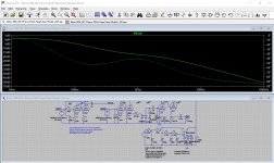
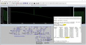
I ran a quick sim in ltspice and it looks like a great performer. Only wonder how quiet the MC input would be, very difficult to implement a tube in that stage. Tempted to design a pcb but already have three tube phone preamps so I must resist 
Besides my skills in pcb design are certainly lacking
Besides my skills in pcb design are certainly lacking
Last edited:
- Home
- Source & Line
- Analogue Source
- Klimo MM/MC Phono RIAA Head Amp Model "LAR" - Schematic wanted