This is a shared DIY project for non-commercial use.
The MA-3D is a 3 channel class D amp suitable for driving a BLWR172S-24-2000 or BLWS231S-24-2000 BLDC motor from Anaheim Automation. The amp is custom designed to work with only these 2 motors; any other motor connected to the output of the amp can permanently damage the amp. The BLWR series has a 4mm shaft and no mounting flange. The BLWS series has a ¼” shaft and a mounting flange that matches up with a Hurst 59 series motor. There are aluminum sleeves available from the RC boat market that will convert 4mm shafts to 3/16" props that will allow the BLWR series motor to work with 3/16" center bore pulleys ie VPI 600 RPM pulleys.
This is not a universal motor controller, it will only work with the 2 motors listed above. If you decide to use a different motor, you are on your own--do not ask me how to make it work for you.
The MA-3D is an amplifier section only and requires the SG-4 sinewave generator to provide the drive signals for each phase. The MA-3D board can also supply the SG-4 with the 12VDC signal needed to power it, so only one wall adapter is needed. The 15V 1A wall adapater included in the BOM powers both the SG4 and the MA-3D. The SG-4 must have firmware version 1.03 or later to work with these motors. V1.01 and 1.02 had a lower frequency limit of 40Hz for 33 RPM and 60Hz for 45 RPM. V1.03 reduces the lower frequency limit to 1.00Hz.
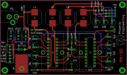
The PCB uses all thru-hole components for easy assembly (with the exception of the 4 inductors which are SMT), but some soldering skills are still required.
The project consists of a bare PCB, a parts "kit" available as a shared cart from Mouser electronics and the on-line documentation you see here.
The PCB is available from OshPark PCB fabricators at the following link: [url]https://www.oshpark.com/shared_projects/mYxj6roI[/URL]
The PCB is created in multiples of 3 for a cost of ~$54 or $18/board.
The parts kit can be ordered from Mouser Electronics: [url]http://www.mouser.com/tools/projectcartsharing.aspx[/URL]
Enter the Access ID code: 90C2DDF260. The parts kit to build 1 PCB costs $55.68.
The following documentation is available below to aid in construction of the project:
MA-3D Schematic.pdf
MA-3D Parts Locator.pdf
MA-3D Assembly Instructions.pdf
MA-3D BOM.pdf (Generic bill of materials with part references)
MA-3D.zip (Gerber X274 files if you want to use your own PCB fabricator)
MA-3D PCB.pdf (X-Ray view of the PCB w/traces, pads and silk screen)
MA-3D.png (X-Ray view of the PCB w/traces, pads and silk screen)
The MA-3D is a 3 channel class D amp suitable for driving a BLWR172S-24-2000 or BLWS231S-24-2000 BLDC motor from Anaheim Automation. The amp is custom designed to work with only these 2 motors; any other motor connected to the output of the amp can permanently damage the amp. The BLWR series has a 4mm shaft and no mounting flange. The BLWS series has a ¼” shaft and a mounting flange that matches up with a Hurst 59 series motor. There are aluminum sleeves available from the RC boat market that will convert 4mm shafts to 3/16" props that will allow the BLWR series motor to work with 3/16" center bore pulleys ie VPI 600 RPM pulleys.
This is not a universal motor controller, it will only work with the 2 motors listed above. If you decide to use a different motor, you are on your own--do not ask me how to make it work for you.
The MA-3D is an amplifier section only and requires the SG-4 sinewave generator to provide the drive signals for each phase. The MA-3D board can also supply the SG-4 with the 12VDC signal needed to power it, so only one wall adapter is needed. The 15V 1A wall adapater included in the BOM powers both the SG4 and the MA-3D. The SG-4 must have firmware version 1.03 or later to work with these motors. V1.01 and 1.02 had a lower frequency limit of 40Hz for 33 RPM and 60Hz for 45 RPM. V1.03 reduces the lower frequency limit to 1.00Hz.
The PCB uses all thru-hole components for easy assembly (with the exception of the 4 inductors which are SMT), but some soldering skills are still required.
The project consists of a bare PCB, a parts "kit" available as a shared cart from Mouser electronics and the on-line documentation you see here.
The PCB is available from OshPark PCB fabricators at the following link: [url]https://www.oshpark.com/shared_projects/mYxj6roI[/URL]
The PCB is created in multiples of 3 for a cost of ~$54 or $18/board.
The parts kit can be ordered from Mouser Electronics: [url]http://www.mouser.com/tools/projectcartsharing.aspx[/URL]
Enter the Access ID code: 90C2DDF260. The parts kit to build 1 PCB costs $55.68.
The following documentation is available below to aid in construction of the project:
MA-3D Schematic.pdf
MA-3D Parts Locator.pdf
MA-3D Assembly Instructions.pdf
MA-3D BOM.pdf (Generic bill of materials with part references)
MA-3D.zip (Gerber X274 files if you want to use your own PCB fabricator)
MA-3D PCB.pdf (X-Ray view of the PCB w/traces, pads and silk screen)
MA-3D.png (X-Ray view of the PCB w/traces, pads and silk screen)
Attachments
Last edited:
Pyramid
You're making this too difficult for me (in a very good way)
I was going to build a set up to control my existing hurst motor with a 2 phase input.
Now this bldc is very tempting. Those motors don't cost nearly as much as I feared. So for a little more $, might as well go for it right?
Again, thanks for all your work and knowledge sharing.

There's no comparison, the Hurst motors are not in the same league, even if driven dual phase. This motor/controller combo is a game changer, everything else is just p*****g in the wind.
By everything else, are you including the Papst flywheel motors running on 3 phase?
twystd
Though I haven't tried the specific motors Bill is recommending, I have experimented with nearly a dozen different BLDC motors, including some high quality Vexta units. In no case could I achieve the vanishingly low level of vibration possible with the Papst outer rotor 3 phase motors.
The inherent problem with the Papst motors is availability; they are no longer made, and have to be bought second-hand, this introduces two issues;
1. Wear. the sleeve bearing is of very high quality, but can suffer some wear with time. It is possible to replace the oilite bushes, but this may be beyond some amateurs.
2. Specs. Obtaining a suitable Papst motor is a bit of a crap-shoot, there are many different sizes and power requirements; you pretty much have to get your motor first, then build the power supply around it.
For the reasons above most people will be more than happy with the solution Bill has come up with; for the few, we lucky few, I think the Papst is ultimately a better solution.
This is a personal opinion only, YMMV.
Last edited:
By everything else, are you including the Papst flywheel motors running on 3 phase?
twystd
Personally, I've not done any testing with the Papst motor, but for all the reasons Ralph stated, this solution is certainly more practical if not an outright improvement.
I would add the AA motors have precision sealed ball bearings so they can handle higher radial loads and won't wear out and get sloppy (vibration) like friction bearings.
It would be interesting to compare the torque output between the AA motor and the Papst. A lot of people refer to the Papst motor as high power; I know they consume a lot of power, but I think they are relatively low efficiency so they might not produce the torque you would think. The flywheel will provide smoothness of rotation and may be unique with those motors.
I would encourage anyone who has the Papst motor to try this solution and report their thoughts on a comparison between the two.
You are right Bill, the Papst motors are seriously inefficient, some quote as little as 6%. They are eddy current motors and rely on the magnetic field in the stator to create the field in the external rotor, which then opposes it. One of the advantages in this is the ability for the rotor 'poles' to be curved, producing a totally cogless rotating magnetic field; in conjunction with the three phases this creates a smoothness that I don't believe can be duplicated with any motor using permanent magnets and an iron core, where there is always some tendency to 'snap' to the next position of 'rest'.
You are right Bill, the Papst motors are seriously inefficient, some quote as little as 6%. They are eddy current motors and rely on the magnetic field in the stator to create the field in the external rotor, which then opposes it. One of the advantages in this is the ability for the rotor 'poles' to be curved, producing a totally cogless rotating magnetic field; in conjunction with the three phases this creates a smoothness that I don't believe can be duplicated with any motor using permanent magnets and an iron core, where there is always some tendency to 'snap' to the next position of 'rest'.
I'm not sure how the AA motors do it, but as far as I can tell, there is zero cogging due to variable reluctance that you described.
On the Hurst motors, this is easily detectable by just rotating the shaft. If you short all the wires together, the cogging is really apparent (the motor is acting as an AC generator with a short circuit for a load).
If you do the same test with the AA motors, it is completely smooth, even the 4 pole motor exhibits no cogging.
The other source of vibration in the AC synch motors, is the coils are wound on 2 separate bobbins that are enclosed by the metal pole pieces rotated 1/2 step between the poles. The bobbins can "float" and can cause vibration at the line frequency. The coils in the BLDC motors are wound on stators that are permanently mounted to the case of the motor so the chance for electrical induced vibrations is greatly reduced.
. . . suitable for driving a BLWR172S-24-2000 or BLWS231S-24-2000 BLDC motor from Anaheim Automation . . .
Very interesting. I'm tempted to send out an order of boards to try this out. Are there people interested in sharing an Oshpark order? 10 boards are slightly cheaper/board than 3 but take longer.
I'm also curious to know what sort of motor pod people are planning to use. I could talk to a local machinist but I wonder if there are off the shelf stand-alone motor pods that would fit the AA motors.
Thanks,
---Gary
I'm also curious to know what sort of motor pod people are planning to use. I could talk to a local machinist but I wonder if there are off the shelf stand-alone motor pods that would fit the AA motors.
Thanks,
---Gary
The BLWS series is essentially a drop in replacement form factor for the Hurst 59 series motors (what VPI uses in most of their tables), but the flange is thicker material so you would need longer mounting screws.
The BLWR series is smaller diameter but longer length then the Hurst motors. It is too tall to fit in the SAMA housing of a VPI. It also has a 4mm shaft and there are aluminum sleeves available from the RC boat market that convert 4mm shafts to 3/16" props that can be used to fit a VPI 600 RPM pulley.
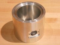
Attached is a CAD drawing for a aluminum enclosure I had made at a local machine shop. They charged me ~$60. The case is cut from a solid aluminum billet 4" diameter on a CNC lathe.
The 1/2" NPT opening on the bottom is so the void can be filled with lead (or steel) shot when the motor is installed. There are 1/2" flush plugs available from McMaster Carr and others. The openings on the motor must be covered if you use small diameter shot pellets.
The connection to the motor is done with a 3 pin miniature mic connector. The socket and connector are available on line at https://vetco.net/products/3-pin-miniature-microphone-connector-male-female-pair.
Attachments
Last edited:
Is one of the motors more desirable than the other from a performance perspective?
Also, I know it must have been discussed, I'm sorry for asking , what is the relationship between the sg4 speed setting and shaft rpm? I know the shaft rpm on one of the motors is double compared to the other.
Also, I know it must have been discussed, I'm sorry for asking , what is the relationship between the sg4 speed setting and shaft rpm? I know the shaft rpm on one of the motors is double compared to the other.
Is one of the motors more desirable than the other from a performance perspective?
Also, I know it must have been discussed, I'm sorry for asking , what is the relationship between the sg4 speed setting and shaft rpm? I know the shaft rpm on one of the motors is double compared to the other.
Performance-wise the motors are nearly identical. If I had to choose, I would say the BLWS series is very slightly quieter, but the BLWR series might have slightly more torque.
The choice really comes down to which form factor and mounting option works best and which pulley option you choose:
BLWR series: Machine a 4mm center bore pulley or use a 4mm-3/16" sleeve and use an existing pulley.
BLWS series: Machine a ¼" center bore pulley.
If there is anyone with some machining capabilities, the attached file has CAD drawings for 600 RPM pulleys for both 4mm and 1/4" center bores.
Attachments
Last edited:
Wow!...this came to fruition a lot faster than I thought it might.
You've out done yourself again Bill! A BLDC motor/controller project "in a box"...I can't thank you enough for this. I think it is really an ideal solution for those in the community looking for a better motor/controller upgrade alternative, especially VPI owners like myself.
It has resorted my priorities concerning my motor/controller projects. I already had a couple of the BLWS motors that I ordered "before the rush". I've got 3 of the amp boards and sets of components on there way now. My first goal will be to finish refurbishing and upgrading my old HW19 and adding this BLDC solution to it as a SAMA.
My only issue will be that the ICs I ordered from Twysted last month are v1.02. Since I have at least one 2 phase controller I intend to follow through on, I will most likely offer what I don't think I will use up at cost and just order v1.03 replacements.
My approach for the pulley will be to pop the VPI pulley into my lathe and bore it out to 1/4".
If there is anyone with some machining capabilities, the attached file has CAD drawings for 600 RPM pulleys for both 4mm and 1/4" center bores.
Can you also attach the CAD files for the pulleys?
My approach for the pulley will be to pop the VPI pulley into my lathe and bore it out to 1/4".
I'd advise against this. Nearly impossible to keep everything concentric. If you have a lathe, turn a new pulley from scratch and do the center bore in the same operation to keep everything aligned.
- Home
- Source & Line
- Analogue Source
- 3 Phase Class D amp for DIY BLDC motor Drive