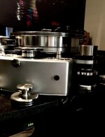
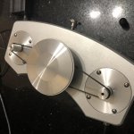
Needless to commend on the size of the sound improvement I am experiencing with my RIM Drive eqquipped with two BLWR172S-24V-2000 motors and precision aluminum pulleys fed by a Class AB amplifier. My VPI Avenger Reference never sounded like this before.
Cant thank enough Pyramid (Bill) for his kindness.
A friend of mine who has a VPI Prime signature, was fascinated with the dramatic improvement and purchased the same motor in order to materialise this thread's project.
The motor was delivered with the power cables plus the HAll cabling.
Should the Hall cables and Hall circuit removed?
If yes how this could be made in a safe for the motor way?
thanking you in advance .
Rim,
I run the BLWR series motor with the wires for the Hall sensors cut off and everything works just as it should.
Thank you for confirming too.
The BLDC rim Drive is producing a stellar sound.
Attachments
Help Help Help
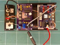
I am building the the SG-4 and the MA-3D and i could not make it work. I am using a BLWS231S motor. When i connect the motor, it stutters. It shaft would rotate a few turns and stop, and then rotate a few turns. I have set up the SG-4 and MA-3D according to the instructions.
The following are the measurements:
SG-4 (output pins)
Standby:
0º 2.485 VDC
120º 2.485 VDC
240º 2.485 VDC
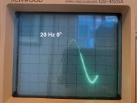
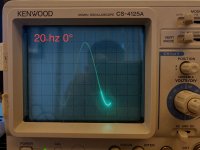
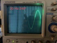
At 20 Hz
0º 2.504 VDC 1.736 VAC
120º 2.504 VDC 1.736 VAC
240º 2.522 VDC 1.734 VAC
At 27 Hz
0º 2.37 ~ 2.627 VDC 1.744 ~ 1.749 VAC (it fluctuates)
120º 2.33 ~ 2.63 VDC 1.744 ~ 1.750 VAC
240º 2.38 ~ 2.65 VDC 1.742 ~ 1.748 VAC
MA-4D
Standby
0º 7.42 VDC
120º 7.42 VDC
240º 7.38 VDC
20 hz
0º 4.2 VAC
120º 4.2 VAC
240º 4.2 VAC
27 hz
0º 4.38 VAC
120º 4.39 VAC
240º 4.39 VAC
The test point, after calibration is at 0.01 VAC
Pin 4 and 5 at U1 are at 1.87 V both, and at Pin 4 and 5 at U2 are at 1.863 V.
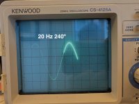
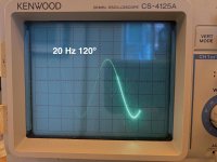
The wave form on a scope looks quite normal too.
Do you see anything wrong with the voltage measurements?
I am building the the SG-4 and the MA-3D and i could not make it work. I am using a BLWS231S motor. When i connect the motor, it stutters. It shaft would rotate a few turns and stop, and then rotate a few turns. I have set up the SG-4 and MA-3D according to the instructions.
The following are the measurements:
SG-4 (output pins)
Standby:
0º 2.485 VDC
120º 2.485 VDC
240º 2.485 VDC
At 20 Hz
0º 2.504 VDC 1.736 VAC
120º 2.504 VDC 1.736 VAC
240º 2.522 VDC 1.734 VAC
At 27 Hz
0º 2.37 ~ 2.627 VDC 1.744 ~ 1.749 VAC (it fluctuates)
120º 2.33 ~ 2.63 VDC 1.744 ~ 1.750 VAC
240º 2.38 ~ 2.65 VDC 1.742 ~ 1.748 VAC
MA-4D
Standby
0º 7.42 VDC
120º 7.42 VDC
240º 7.38 VDC
20 hz
0º 4.2 VAC
120º 4.2 VAC
240º 4.2 VAC
27 hz
0º 4.38 VAC
120º 4.39 VAC
240º 4.39 VAC
The test point, after calibration is at 0.01 VAC
Pin 4 and 5 at U1 are at 1.87 V both, and at Pin 4 and 5 at U2 are at 1.863 V.
The wave form on a scope looks quite normal too.
Do you see anything wrong with the voltage measurements?
Attachments
All the voltages you report look OK as does the waveform on the scope.
Does the motor spin freely by hand when disconnected?
You could also try measuring the DC resistance of the windings from leg to leg; they should be very similar.
Edit: I just looked closer at one of you pics of the scope; it appears to be set to 1V/div and the waveform is ~4.3 divisions. If this is correct, then the voltage is 4.3VPP not 4.3VRMS which would be ~12VPP.
Last edited:
Hi Bill,
really appreciate your guidance on this.
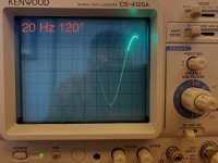
I may have uploaded the wrong photos at the last post. So I have measured again, and the voltage on the scope is a little lower than 12Vpp. So i adjusted the trimpot so that all three phases at displaying 12 Vpp (6 divisions at 2V/div). I have attached the photos here of the scope trace without load.
The measured VAC at 0º, 120º and 240º are 4.47Vac, 4.51v, and 4.45v.
Then calibrated the TP to 0.02 vac.
The motor still stutter.
I measured the 0º AC output while the motor is on and the voltage jumps all over the place. I have included a video shot of my meter while taking the voltage.
The signal on the scope while the motor is running shows distortion.
I have put the video clips of the scope trace and the multimeter reading of the 0º lead on a dropbox folder:
Dropbox - For Bill - Simplify your life
Appreciate if you can take a look and see if you can spot what is going wrong.
really appreciate your guidance on this.
I may have uploaded the wrong photos at the last post. So I have measured again, and the voltage on the scope is a little lower than 12Vpp. So i adjusted the trimpot so that all three phases at displaying 12 Vpp (6 divisions at 2V/div). I have attached the photos here of the scope trace without load.
The measured VAC at 0º, 120º and 240º are 4.47Vac, 4.51v, and 4.45v.
Then calibrated the TP to 0.02 vac.
The motor still stutter.
I measured the 0º AC output while the motor is on and the voltage jumps all over the place. I have included a video shot of my meter while taking the voltage.
The signal on the scope while the motor is running shows distortion.
I have put the video clips of the scope trace and the multimeter reading of the 0º lead on a dropbox folder:
Dropbox - For Bill - Simplify your life
Appreciate if you can take a look and see if you can spot what is going wrong.
Attachments
The 0° output is definitely oscillating, but I'm not sure why. One possibility to check: Another user reported faulty operation and the DC voltage on the input cap was lower than the bias voltage on the other side of the cap (input pin of U1 chip amplifier). The tantalum caps on the input are polarized, so reversing the polarity (or replacing them with a non-polarized cap of the same value) cured the problem.
I have changed out all the capacitors on the MA-4D. I have changed out the IC amps. The problem still persist. I have tried different PSU and one of them is a AMB sigma 22 regulated power supply at 15Vdc. I am really at a lost. I am thinking of starting again with new boards and new components.
Is there anyone on the forum still have spare boards that i could buy.
Is there anyone on the forum still have spare boards that i could buy.
Hi Bill,
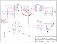
I notice that the polarity of C9 on the schematic vs on the board is different. On the board the positive terminal is connected to R4 and negative to ground, but on the schematics, it's the reverse. On the board, i have connected the 6.8u with positive to R4 and negative to the ground. Would this cause any issue.
I notice that the polarity of C9 on the schematic vs on the board is different. On the board the positive terminal is connected to R4 and negative to ground, but on the schematics, it's the reverse. On the board, i have connected the 6.8u with positive to R4 and negative to the ground. Would this cause any issue.
Attachments
- Home
- Source & Line
- Analogue Source
- 3 Phase Class D amp for DIY BLDC motor Drive