Also, can you tell me how much current goes through each pushbutton on the SG4?
The µP pins have 50K internal pullups; at 5VDC a switch to ground will conduct ~100uA.
I've built a couple of these amps and they worked like a charm. The 3rd one turns out to be a problem. The motor would not hold a constant speed. It turns out that the voltage on the 0 degree output of the amp fluctuates constantly - plus/minus 1 volt from a set point of 4 volts - even with a stable input from the SG4. Fortunately I had another board and swapped it out. Any thoughts on what could be causing the problem or how to troubleshoot would be appreciated. Maybe the chipamp?
Thanks.
Thanks.
Hi Bill... sorry to bother you again about this but my speed issue returned. The motor is drifting when hot and the voltage on u1/pin 19 is increasing over time, reaching 8.6 VDC after a couple hours. The ics are also getting hot, even with the heatsinks on.
This would be the second defective ic so I must ask what could be causing this? Something must be damaging those ics...
the SG4 is stable as a rock, delivering 2.52VDC for each phase, with a frequency setting of 20.82Hz. Both ics/pin1 is 14.85VDC. u1/pin12 = 7.49VDC, u2/pin = 7.60 VDC. TP1 = 0.024VAC
Current consumption for the whole system (SG4,MA3D,Motor) is 385 mA.
All measurements were taken with the motor on and after 2h running.
Could it be a defective motor? Defective potentiometer? any other idea?
Last edited:
It sounds as if IC1 is bad again. Not sure what is causing it. Can you check that L3 and C15 are the correct values? You might try replacing C5 (or check that the polarity is correct). I'm using the same circuit (although SMT parts rather than DIP ICs) for 4+ years and never had a problem. Check the line to line resistance of the motor (all three should be the same).
Thanks for the reply, Bill!
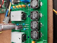
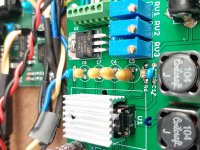
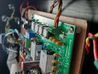
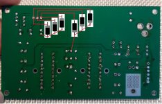
So, I´ve ordered everything from mouser, using the cart. Double checked before soldering and I believe everything is right. Either way, I´ve checked the values again today and took some photographs (I don´t know why, but every photo I upload here gets rotated. weird.)
Regarding the motor, I´m getting the following resistances:
yellow & red = 6.8R
red & black = 9.2R
yellow & black = 9.2R
They´re not the same! The BLWS231S-24V-2000 datasheet states that the value should be 6 for all of them, as you said before.
Can I assume the motor is damaged, then? The resistance difference would cause an unbalance rotation, stressing the IC and damaging it?
I do have a spare motor and the measurement is 6.4R for all three wire pairs.
I do not know much about motors, but could a bad IC damage the motor? Or can I assume it is a factory defective unit?
Attachments
Something is not right with the motor. I doubt the ICs damaged it, probably the other way around. If you have a spare motor, I would definitely use that one.
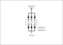
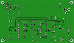
One other thing you can add (just in case): Add diodes to the outputs of the PCB as shown; this will protect the amps from any voltage spikes caused by the motor, especially if if the wires are disconnected while power is applied.
One other thing you can add (just in case): Add diodes to the outputs of the PCB as shown; this will protect the amps from any voltage spikes caused by the motor, especially if if the wires are disconnected while power is applied.
Attachments
Yeah, I´ll swap the motors later today.
I´m a little confused about this image, I must add 6 diodes?
Earlier, when measuring the motor resistances, I was considering soldering three 1N4004 or 4148 diodes (it´s what I have now) inside the motor pod, one for each wire, on the xlr socket, to prevent feedback current going back to the pcb. Wouldn´t that work?
Last edited:
Do not add the diodes in series. The current needs to flow into each motor wire as well as out of the motor. The 6 diodes added as shown in my diagram are all reversed biased in normal operation; they only conduct (forward bias) if the voltage on any lead goes above 15VDC or below ground and act as shunts to protect the amp IC. The voltage on the output pin of the IC will always be: -0.6V<Pin<15.6V.
Add the diodes at the output connector. The diodes to ground can parallel the tantalum caps. A better place would be right at the output pins of the IC (pins 12 & 19 of U1 and pin 12 of U2). Pin 1 and pin 10 of U1/U2 are 15VDC.
Add the diodes at the output connector. The diodes to ground can parallel the tantalum caps. A better place would be right at the output pins of the IC (pins 12 & 19 of U1 and pin 12 of U2). Pin 1 and pin 10 of U1/U2 are 15VDC.
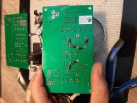
Ok. I've installed the diodes, replaced the motor (with the power cord, the resistance increased to around 7R for each wire pair) and replaced U1. I've done the calibration process again but after a while the voltage on ic1/pin 19 is increasing again, with a value of 8.32VDC right now. The motor speed is decreasing as the voltage unbalance increases.
Attachments
What happens to the voltage at pin 19 if you run it without the motor connected?
The only thing that I can think of, is one of the tantalum caps is leaky (C5 or C15); what is the DC voltage on either side of C5 (measured to ground)?
The other possibility is the IC is defective; are you replacing the ICs with prime parts or are they purchased from an unreliable source? Have you tried replacing both ICs at the same time?
Bill, all the parts (for both SG4 and MA3D) were purchased at Mouser.
I did replaced both ICs last time, because I was unable to desolder the ic1 so I went with a full board transfer and installed ic sockets.
Last night, when it reached 9VDC, I disconnected the motor and the voltage was still around 9VDC, but the ic was still hot...
I´m running it now, without the motor, and I´ll keep measuring the voltages.
I´ll get back to you.
I still have spares for every part, not enough to build a new board from stratch tough.
I still have one spare TPA ic but if it´s gone it will be impossible to get another, as mouser isn´t shipping to Brazil anymore (for the time being).
measurements right now (15 min running - no motor):
20.79Hz
output block
0=7.92VDC
120=7.64VDC
240=7.82VDC
TP1=0.03VAC.
C5 = + 0.6VDC / - 1.81VDC
C15 = + 7.64VDC
It might be more accurate to take readings with the SG4 in standby. I just measured my MA3D and the DC voltage on the IC side of C5 was +1.8VDC. The SG4 output will be +2.5VDC, but if the pot is near it's low side, the DC voltage will be lower than 1.8V to the input side (+) of C5, so that may be causing the leakage. If you have spares, try replacing C5, C6 & C11, but reverse the polarity so the + side is towards the IC (if you have non-polarized caps of the same value, those will work as well). If you don't have spares, just change the polarity of the existing parts (that small of voltage/current should not have damaged the tantalum caps).
The outputs of the MA3D should be very close to 7.5VDC with the SG4 in standby. The fact that all 3 of your output voltages are high indicates leakage on all 3 inputs (or your meter is being thrown off by the presence of AC at the same time).
The outputs of the MA3D should be very close to 7.5VDC with the SG4 in standby. The fact that all 3 of your output voltages are high indicates leakage on all 3 inputs (or your meter is being thrown off by the presence of AC at the same time).
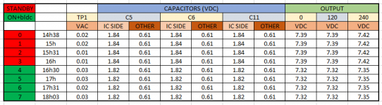
So, replaced and inverted all three caps and measured the voltages during ~3h30. The results are attached.
The motor was out of the POD and it´s temperature after a while was stable at 47°C/116.6°F.
It seems that inverting the caps was the solution and the ic1 was not damaged during yesterday´s test.
What do you think, Bill?
The motor was out of the POD and it´s temperature after a while was stable at 47°C/116.6°F.
It seems that inverting the caps was the solution and the ic1 was not damaged during yesterday´s test.
What do you think, Bill?
Attachments
- Home
- Source & Line
- Analogue Source
- 3 Phase Class D amp for DIY BLDC motor Drive