It almost sounds as if something got into the bearings. While they are sealed, it is possible to contaminate them if the debris is small enough.
When I was machining one of the motor cases, I left the rotor/bearings in place because I didn't want to take the motor all apart for a couple of small holes. The metal filings got into the bearing and it remained noisy.
There is not anything the controller or amp can do to damage the motor. You might want to check if the outputs of the SG4 and MA-3D are still sinewaves, but other than that, I think something happened to the bearings.
Some people have replaced the bearings with higher precision types; check previous pages in this thread for info.
Cleaning did not do any good, but I went to my machinist and he changed the bearings to the following types (for the BLS motor) : Deep groove ball bearings - 608-2RSH Deep groove ball bearings - 607-2RSH and everything is quiet again.
It just puzzles me that the motor was one month old. It looks that the bearings are low quality, but can easily (by a machinist) be replaced to a quality type ones.
It just puzzles me that the motor was one month old. It looks that the bearings are low quality, but can easily (by a machinist) be replaced to a quality type ones.
Hi Pyramid,
I plan to use the SG4, the MA-3D and the BLWS motor for a Thorens TD 125. I decided to increase the pulley diameter to 0.5", so I need 407RPM/549RPM for 33/45. The frequencies are 13.57Hz/18.32Hz.
What should be the nominal and reduced motor voltages for these RPM values? Is there an easy way to calculate these myself? Thanks in advance.
Thank you Pyramid.
The AA motor - MA-3D - SG4 setup works very nicely.
One thing I noticed is that the motor stops instantly when going back into standby. Just thinking, would it be possible to provide a slow, ramped down stop? Maybe this would need to slowly decrease the frequency to almost 0Hz in 3 - 4 sec? Is there an easy way to do that in the SG4? I'm thinking heavy platter needs to stop, so the belt needs to give (expand) or slip on the already stopped pulley. Also, this would need to be optional, as some would use the SG4 to drive step-up transformers to mains voltage through an amp, where this is not needed at all. Just a thought.
Last edited:
I am out of my depth here, so I will cry for help/instructions.
I have assembled both the SG4 and MA-3D as per the guides.
Note: Using a True RMS DMM (Brymen BM235)
Where:
(B) Black probe on COM
(R) Red probe on Ohm/V
Turn on DMM, selector to V (this one has VAC and VDC on the same selection)
Measure:
SG4
I get the correct voltages as per the guide on:
U2 Pin 4
(B) Gnd on output point and (R) U2 Pin 4: 7.96V
U3 Pin 16
(B) Gnd on output point and (R) U2 Pin 4: 5.00V
On the SG4 out points, in standby mode, I get:
(B) on Gnd and (R) on 0 deg: 2.5V
(B) on Gnd and (R) on 120 deg: 2.5V
(B) on Gnd and (R) on 240 deg: 2.5V
In Reduced Voltage mode (Dn + Stby) at 128, I get the same values as above.
MA3D with SG4 in Reduced Voltage Mode (128)
On SG4 In (SG4In) side only (P2)
(B) Top Gnd (TG) and (R) 12V: 12V (powers SG4)
(B) Bottom Gnd (BG) and 0 deg: 2.5V
(B) Bottom Gnd (BG) and 120 deg: 2.5V
(B) Bottom Gnd (BG) and 240 deg: 2.5V
Where do I put (B) and (R) to get the 4.2VRMS at P3 for:
0 deg?
120 deg?
240 deg?
Can I use a True RMS DMM?
Is there a way to test the MA-3D without the SG4 connected?
I tried (adjusting RV1, RV2, RV3 respectively):
(B) SG4In (P2) 0 deg and (R) Motor Out (P3) 0 deg: fluctuating 4.1V-4.3V
(B) SG4In (P2) 120 deg and (R) Motor Out (P3) 120 deg: fluctuating 4.1V-4.3V
(B) SG4In (P2) 240 deg and (R) Motor Out (P3) 240 deg: fluctuating 4.1V-4.3V
(B) SG4In (P2) BG and (R) TP1: 0.0346V
The BLWS231S-24-2000 BLDC motor spins but it vibrates/cogs (rattling dance on the table top) at 45rpm. Possibly at 33rpm too but too weak to feel by hand.
I know I am doing it all wrong. I don't think I am looking at the VRMS values at the measurements above for the MA-3D. Please teach me how to swim.
Many thanks.
The voltages look correct for DC volts, not AC. Try using the manually selected AC volts function on the meter.
Measure the 4.2VRMS output with the (R) lead on 0/120/240 pin and (B) on Gnd at input connector.
The motor will benefit from some mass loading; mounting it to metal enclosure will prevent vibrations from starting.
Measure the 4.2VRMS output with the (R) lead on 0/120/240 pin and (B) on Gnd at input connector.
The motor will benefit from some mass loading; mounting it to metal enclosure will prevent vibrations from starting.
Hello Bill,
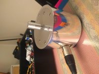
I've finally finished the MA3D and motor replacement, with a pod and pulley made of aluminium by your designs.
The alignment voltages are 4.2 VRMS on each phase, with the reduced voltages matching the original instructions.
I'm running a VPI prime, with 2 belts, and using the arduino tach, 33 RPM is achieved with 20.86Hz and 45 RPM with 28.17Hz.
I'm facing some issues, with the motor starting to vibrate and losing speed.
Could it be because of the different frequencies and lack of voltage compensation? What should be the correct voltage values?
The finished motor assembly has 1240g, almost 1000g less than the original VPI SAMA. I'll add lead shots to reduce this difference.
Thanks in advance for your help.
Attachments
Last edited:
The frequencies are not that far from the original, it is not that sensitive. Make sure the DC voltage on all 3 outputs is the same (±100mV).
Does the motor run normally before the reduced voltage? If the reduced voltage is too low, you can try increasing it slightly, the trade off will be increased heat.
The motors can vibrate more if unmounted and held in your hand. Mass loading helps prevent the vibrations from even starting. The case should be more than adequate, but lead shot may help.
If you dis-assembled the motor to remove the hall sensors, make sure the wave washers pre-load the bearings are both in place (top and bottom).
Nice looking case/machining BTW.
Thanks.
I did not remove anything from the motor, just trimmed the wires and isolated the ones that would not be used.
I've added almost 900 g of lead, but the vibration is still present, regardless of voltage settings. The motor starts fine and the vibration slowly builds up until noticeable, with impact of rotation stability.
Without the motor connected and in 45 RPM, 128 reduced voltage setting, I'm getting stable
7.76VDC for 240, stable 7.82 VDC for 120 and a lot of fluctuation for 0, ranging from 8.9 until 10.
SG4 outputs 2.52 VDC for each phase.
Without the motor connected and in 45 RPM, 128 reduced voltage setting, I'm getting stable 7.76VDC for 240, stable 7.82 VDC for 120 and a lot of fluctuation for 0, ranging from 8.9 until 10.
The DC outputs of the TDA3123 chips should be roughly half of the DC supply voltage. The fact that zero deg output fluctuates is a potential problem. Look at the TDA3123 outputs when the SG4 is at standby; the DC should be supply voltage/2 and should have 50% duty cycle square waves (AC). It might be helpful to look at both the inputs to the chip amps and the outputs with a scope.
Checked the solders, reflowed them all, problem not solved.
All the caps are installed correctly so I decided to change the amp ic. A LOT of work after (with 2 pads damaged, but fixed with jumpers) and now I'm getting:
U1: pin 12 7.52 VDC, pin 19 7.56 VDC
U2: pin 19 7.54 VDC
TP1: 0.039VAC
Now I'll reassemble everything and test with the motor.
All the caps are installed correctly so I decided to change the amp ic. A LOT of work after (with 2 pads damaged, but fixed with jumpers) and now I'm getting:
U1: pin 12 7.52 VDC, pin 19 7.56 VDC
U2: pin 19 7.54 VDC
TP1: 0.039VAC
Now I'll reassemble everything and test with the motor.
Everything is working as it should now. The motor is on for quite some time and no vibration or speed loss whatsoever.
For those starting to build the amp, I strongly recomend to use dip sockets for the ICs (and buy one IC extra, doing it sure paid off for me).
Thanks for everything Bill!
For those starting to build the amp, I strongly recomend to use dip sockets for the ICs (and buy one IC extra, doing it sure paid off for me).
Thanks for everything Bill!
I have built an SG-4 driving an MA3 for BLWR172S motor. The platter/bearing is from a VPI TNT. I'm having some odd behavior. The speed will vary from 33.327 steadily up to 33.348 and then beck down to about 33.327. It just keeps cycling up and down and is really fairly consistent. I'm measuring RPM with a Phoenix Engineering Roadrunner. For the size pulley I'm using (one from SDP/SI) I need about 36.15Hz to the motor.
I've balanced the controller a couple times but wonder if there's still a problem, given how regularly it cycles up and down.
Any thoughts will be greatly appreciated.
For reference, this is my second SG4/MA3 setup. The first is BLWS231S motor, powering a VPI Scout table. It works perfectly. I'm wishing I would have used the BLWS motor on the second table also.
Make sure the belt is not twisted or that it is not riding up/down on the platter or pulley. If I have been handling the belt a lot, I clean the belt, pulley and platter with alcohol (do not powder the belt as VPI suggests). I assume the bearing is lubed properly?
The belt seems to be straight. It's a new belt. 1/8" to match the pulley. The beari g is libricated and in good condition.
I was wondering if I was getting a beat frequency since the variation seems to be so regular.
Ill try readjusting the MA3.
- Home
- Source & Line
- Analogue Source
- 3 Phase Class D amp for DIY BLDC motor Drive