Remember the spice files I sent you a while ago for the version with 300x gain at 1kHz ?
In spice at least, THD is quite decent at 2Vrms out, using 4x 2SK372 at the input.
Maybe you would have another look at see if I have done something really silly......
Patrick
Will do, I'm not fully set up with LTSPICE on my new laptop. Could you resend just to make sure to my gmail account some things got mixed up with my retirement.
EDIT - I found the one with 2SK170's and 200 Ohms degeneration, I will look at it more closely. What I worry about is reducing the degeneration of the folded cascode and at the same time increasing the impedance level of the RIAA network will make parasitic capacitances/resistances have a larger role.
It might all work out that we can have it all, but I would like to have a version that uses the Linear Systems FET's so folks don't have to worry about obsolescence and fakes.
Last edited:
I guess you are not hired by LS to come up with application examples for them ?
Patrick
To be clear no, not one cent. I've worked with John Hall (RIP) since 1977, but in that case I was paid by my day job.
I feel that Scott's new discrete circuit has a lot of merit, and the topic that it includes is worth contributing to, especially on this thread. Scott has the skill and parts to do world class work, and that is what we should discuss.
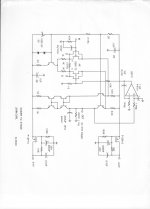
Here is one example of one of my similar designs, taken as Scott did, from the AD797 topology and its predecessors (Harris), that I made for Parasound, but they decided not to build but a few prototypes.
There are a few differences, please note the use of bipolar parts for the second stage. (Parasound did not want to use any more pch jfets than necessary), servo (IC designed by Scott), and a number of other features. Parasound got the right to first refusal, so I can publish it now. Scott's design has other advantages, and perhaps we might discuss the general design together, with any one else invited to contribute.
Attachments
Last edited:
My headphone amp uses that topology as its first two stages: NJFET diff pair -> PNP folded cascode -> enhanced NPN current mirror. But I've added a double EF output stage to drive 15 ohm loads; John has no 3rd stage so he's got a transconductance amp driving a 2.62K load resistor. I felt it was important to heavily bypass the PNP folded cascode transistors' bases, to the top rail, so I used 100uF + 0.1uF. John's schematic doesn't include these.
And we can wonder aloud whether the 220uV 35V capacitors on the gate nodes of the capacitance multipliers, are "less harmful" than an electrolytic bypass capacitor would be on the supply rail itself. Since the MOSFET is a unity-gain source follower, any electrolytic-caused badness on the gate, gets copied onto the source, n'cest pas?
And we can wonder aloud whether the 220uV 35V capacitors on the gate nodes of the capacitance multipliers, are "less harmful" than an electrolytic bypass capacitor would be on the supply rail itself. Since the MOSFET is a unity-gain source follower, any electrolytic-caused badness on the gate, gets copied onto the source, n'cest pas?
Was just pulling your leg.
Documents sent by email.
Patrick
I know, thanks if we could squeeze in the extra gain without sacrificing other parameters it would be an improvement.
Thankyou John, if one can make an open-loop phono stage with -87dB THD it deserves a listen. The circuits all come from the past that is not important.
Can't speak for others but I avoid them myself because they gobble too much voltage headroom, and because the unit to unit variability of output conductance seems to be greater in discrete MOSFETs than in discrete BJTs.I wonder why FET mirrors are not used more widely ?
Have you considered a full 4T Wilson mirror using BJTs next to the rail and FETs next to the signal nodes? Perhaps you'll like it better than four identical devices, either BJT or FET? The BJTs only see a volt of VCE so you can use superbetas if you want.
For my particular application, voltage headroom is no issue, just raise rail voltage.
The Zetex MOSFETs I tried offered very good match even in a small batch of 25.
With matched Vgs, variation in Yfs is very low.
It is true that BJTs can do away with matching.
But then we match FETs all the time, so no big issue.
Patrick
The Zetex MOSFETs I tried offered very good match even in a small batch of 25.
With matched Vgs, variation in Yfs is very low.
It is true that BJTs can do away with matching.
But then we match FETs all the time, so no big issue.
Patrick
SW --- can we get more detailed spec numbers pls. I am always criticized for not doing so... so its my turn. THD from 20Hz to 20Khz and at what level and load Z?... and PSRR on each supply from 20Hz to 20KHz.
All without the RIAA EQ elements... so we see only the circuitry doing its thing.
You ought to go one better and use the dc servo and not electro caps.
THx-RNMarsh
All without the RIAA EQ elements... so we see only the circuitry doing its thing.
You ought to go one better and use the dc servo and not electro caps.
THx-RNMarsh
great! thanks for answering my question before i asked.
")
mlloyd1
mlloyd1
There was some 100MHz fur probably gate stoppers would also get rid of it but that would involve cutting and soldering and I already killed one 75n poly cap by just brushing it with a hot iron.
SW --- can we get more detailed spec numbers pls. I am always criticized for not doing so... so its my turn. THD from 20Hz to 20Khz and at what level and load Z?... and PSRR on each supply from 20Hz to 20KHz.
All without the RIAA EQ elements... so we see only the circuitry doing its thing.
You ought to go one better and use the dc servo and not electro caps.
THx-RNMarsh
The DC servo is your opinion (they are polystyrene caps BTW) and I don't respond to demands.
Yes, for a music signal this is >4V p-p at even at a crest factor of 3 which would already be railing your PA in most cases. I always wonder if I'm missing something 4V into a PA with 26dB of gain puts 80V on your speaker, is that wrong?"Distortion at 1K with .025Vrms in, ~-87dB ....." Gain at 1kHz was 26dB.
So output is 0.5Vrms ?
Patrick
Richard was just making a friendly suggestion in order to upgrade your design.
Upgrading is not necessary, This is supposed to be a fun exercise that anyone can do, searching for and paying for obsolete devices just turns people away.
Last edited:
... and I don't respond to demands.
I support you.
My equivalent reply is "I don't take requests" because it seems to infuriate the demand-er just a bit more. But you and I may have different appetites for schadenfreude perhaps.
- Status
- This old topic is closed. If you want to reopen this topic, contact a moderator using the "Report Post" button.
- Home
- Source & Line
- Analogue Source
- A simplified universal differential or single ended phono preamp