Posted in here as a lot of people don't appear to check the software thread often !
Nice & useful free App, & i havn't seen anything similar elsewhere.
Introduction
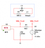
Desire to compute an accurate model of the LCR response of the phono input loop led to these calculations and calculator. Figure 1 represents what I believe an accurate model of this circuit
Website of Wayne Stegall - Phono Termination Calculations and Calculator
Nice & useful free App, & i havn't seen anything similar elsewhere.
Why would someone wish to model the LCR response? In most cases it will be swamped by the mechanical response, so in most cases it will lead people seriously astray.
^this.
If one 'optimises' LCR response in isolation, then overall response, ie what matters, is near certain to be non-optimal. This is because there is typically an audioband mechanical system response, which is independent of the electrical response, so cartridge designers work LCR and mechanical systems together for an overall result.
LD
A further comment: any such model assumes inductance is ideal, whereas in practice it often isn't IME. Losses might vary with level, frequency and/or slew rate of programme material, and I found some evidence a few years back that inductance itself might effectively vary with such parameters. I eventually formed the view that is all part of the character of the cartridge, and perhaps vinyl sound, after some fairly hairbrained schemes to use a 'passive' or dummy cartridge as part of termination as a means to avoid such effects.
Halcyon days !
LD
Halcyon days !
LD
I seem to recall that a Mr. Halgren (?) proposed a more complicated model than the simple low pass filter in the JAES in the 1970s. He added some additional resistors to account for other losses. A respondent pointed out that the calculated results using the complicated model weren't much different than the results of the simple model so there was no big rust to use the complicated model.
Here is the correct derivation of the formula for the cartridge electrical Q assuming the simple low pass filter model.
Line 1 is the transfer function and Rs is the cartridge resistance and Rl the load resistor.
Line 2 is just some definitions and these definitions are put in the transfer function in line 3. The second term in the denominator contains some time constants and the inverse of a time constant is a frequency. Line 4 shows what the frequencies are. Line 5 shows that Qs sum like resistors in parallel and finally we get line 6. You then equate the second term in the denominator of line 6 to the second term in the denominator of line 1. After some manipulation you have line 7 which is the correct formula for the Q. You can obtain several formulas depending on the substitutions used, so why is this formula the correct one? If you solve the line 7 formula for C you have to solve a quadratic. However every case I've tried, the denominator is just a little larger than 1.0, it might be 1.02 or 1.05 so usually you can ignore the denominator and solve the formula in line 8 for the approximate Q. That formula is so simple I can do it on my fingers, if I don't have to count above 10. Line 9 is the formula for the cutoff frequency where the response is down 3 dB.
Attachments
Last edited:
Bjorn Hallgren 1975. Somewhere I have the actual paper reference, but didn't feel need to pay $33 for the paper. The model Rod Elliot proposed I believe is more advanced than the Hallgren model.
https://linearaudio.net/sites/linearaudio.net/files/lte_vol3_1.pdf second letter has a bit of analysis looking at it from the point of cancelling the mechcanical resonance with an inverse filter.
Of course all this t*rd polishing is only of interest if you don't like the idea of a peaked response with 4th order roll off. And if you have the right cartridge then you are flat to over 20kHz provided you have a low enough input C on your phono pre-amp. Many don't and complain a cartridge is bright when in fact its just wrongly loaded.
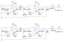
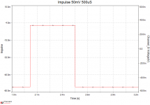
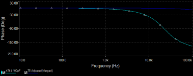
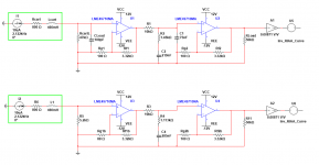
At the moment, I am going to use the "simple model" -- for a passive RIAA correction the first with the 75us pole a la Lipshitz 1C, and the second the cartridge loading resistor "tuned" to just a bit higher than 75us (64uS) and a 1uS pole in the passive network. (Figure1). The two are gain adjusted for near identical response at 1kHz.
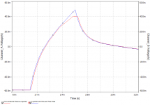
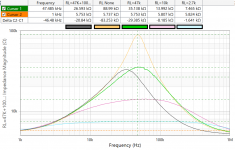
So, wondering how this would be affected by an impulse, I put a 50mV 500us pulse in both,
So, wondering how this would be affected by an impulse, I put a 50mV 500us pulse in both,
Attachments
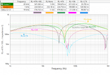
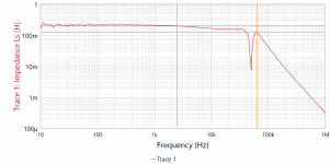
I have a Shure M78 for playback of 78's -- they basically placed in parallel the two halves of a stereo cart. I use a 5k Caddock and -10dBm source to deliver about 18uA to the cartridge from 1kHz to 1MHz. The setup is standardized so that there's only a few pF of residual capacitance.
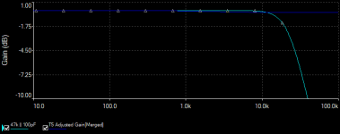
The attached should be pretty self-explanatory. The usual 47k||100pF might not be optimal -- but whoa, the maths!
The attached should be pretty self-explanatory. The usual 47k||100pF might not be optimal -- but whoa, the maths!
Attachments
Last edited:
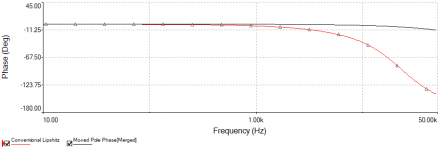
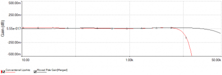
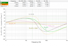
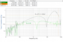
Another chart. I thought that averaging would help. It doesn't. The task now is to make two identical preamplifiers with two loading systems and compensation networks, see if there is a detectable difference, and a betterment of one versus the other.
Attachments
Last edited:
")
So, we can do this -- substitute LM4562 for LME49710 in each case. The gain setting resistor in the T5 compensated amplifier is lowered to 88 ohms so that the gains of both amplifiers are almost exactly equal. a 1us pole replaces the 75us pole so that some of the values change.
I'm open to suggested recording torture tests. We've used "Rachmaninoff Symphonic Dances, Funeral March Andante con moto (tempo di valse), Reference Recordings 5" -- good (excellent) if you can find it.
I'm open to suggested recording torture tests. We've used "Rachmaninoff Symphonic Dances, Funeral March Andante con moto (tempo di valse), Reference Recordings 5" -- good (excellent) if you can find it.
Attachments
- Status
- This old topic is closed. If you want to reopen this topic, contact a moderator using the "Report Post" button.
- Home
- Source & Line
- Analogue Source
- Phono Termination Calculations and Calculator