I have recently had need of a free-standing Mag PU preamp, and resurrected a design I have often used in the past. It is based on the NE5532 dual low noise IC, includes a 25Hz 12db/oct HP filter, and may be powered by a couple of PP3s. It performs extremely well, despite the design being rather long in the tooth, and does not cost an arm and a leg to produce.
I thought it might be of interest to some of yous, and I have zipped up a set of files (324Kb) including the schematic and PCB layout. I'll be happy to send it on receipt of an email request. I can also provide a (higher) res image of the PCB track layout, or Gerber files (if you don't know what those are, you don't need them!) on request.
JohnT
Attachments
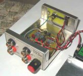
The circuit.
Hi John,
There are many phono preamp circuits right here on this forum.
The NE5532 is a pretty good opamp despite its age.
However in a phono preamp that I built recently , I found the Ad826 or even the OPA2134 sounded better at LF and in percussion sounds-than a NE5532. Have you made any such comparisons?
It would be interesting to see what the circuit is like.
You could post it on the forum or maybe you could email it to me.
amadhavan(at)yahoo.com
Thanks.
Cheers,
ashok.
I know there are several other pin compatible ICs which are considered more desirable than the 5532, and in my earlier days I tried (literally) dozens of different preamp designs - discrete, balanced, FET, passively equalised, single IC, multi IC ............ I was always paranoic about noise level, which kept me away from MC cartridges for some years, and although I've still got a couple lying quietly in their boxes, I'm happy to use a MM for what little exercise I give my vinyls. And I'm equally happy with the 5532 - it does exactly what it says on the box!
JohnT
JohnT
Thanks.
Hi John,
Thanks for the zipped file. I simulated it and found that the rumble filter cuts off too early for my liking. I would say that the RIAA error with filter should not be more than -3db at 20 Hz. That way the bass will be intact and the LF from the turntable will be minimised. Additionally the HF error shows a rising trend after 20KHz . That might make surface noise more irritable.
I will try to work on this and send you a modified circuit. Since you have already got a circuit board , I will stick to change of component values. I did some quick mods and there was an improvement . I will also build the circuit and test it with various OP amps. Will let you know results soon.
I like the idea of running the whole thing off a battery. Great circuit for beginners. Maybe you should sell the bare pcb's on the net.
Another thing I was concerned about. I never like to apply ac signals or pass ac signals through a non biased Elec cap. In your case it might be better to run the whole amp from 18 volts (9+9) with ground on the -ve supply. That way all Elec Caps will get polarised at 9 volts or so. In this circuit input and output is dc decoupled and so there should be no problem. Check it out.
Cheers.
Ashok.
RIAA Eq
Hi Ashok
I can't get too worked up about the LF turnover point. If you're using a pair of loudspeakers in the 20K bracket (£ or $ - I doubt the exact amount matters that much at that level) then what happens around 20Hz may be of interest. But for those of us who have to manage with more frugal offerings, which can be fitted into the space allowed between the wife's set of vases and, maybe, the kid's Scalectrix, then 20Hz only exists in dreams!
My loudspeakers are 6db down at 40Hz (20W75 in 1 cub ft, nearfield), and will be somewhat better than that when room gain is taken into account. But, 20Hz .... well .................
So far as the rising HF error is concerned, this is a well known drawback with series feedback equalisation. Parallel feedback, or passive equalisation topologies, can better approach the ideal, but series feedback designs give lowest noise floors. You pays yer money and yer takes yer choice! None the less, I do not recall trying to minimise out-of-band error when I put this design together many years ago (using standard values for R and C), and no doubt the measured error could be improved. But ..... while my loudspeakers limit what I can get at the bottom end, my ears no longer respond to anything above about 9KHz at the top. So it may be that some wealthy youngsters will have to be the beneficiaries of any improvements you come up with. But don't let that stop you trying!
JohnT
RIAA Eq
Hi again Ashok
Forgot to address the Electrolytics question.
Yes, it's true that use of a single ended supply, and a shift of the DC reference point, would ensure absolute polarisation of the electrolytics. However, recent research suggests that polar electrolytics are at their most linear when polarising voltage is low, and I seem to remember that this is maintained with low levels of reverse poarisation. Better still, and best, is apparently to use non-polar electrolytics, which can approach the performance linearity of solid dialectrics, but with high values and low bulk. (See series of articles by Cyril Bateman in Electronics World over the past year or so).
JohnT
To tweak or not to ?
Hi John,
You are right about the unity gain limit causing the error at HF. I had overlooked that till I tried to tweak some parts and looked at the actual stage gain.
That information about the electrolytic caps is interesting and reassuring. I used to get Wirless World regularly till a few years ago. I must search out the past issues .
About tweaking the parts, I am sure the improvements will probably not make any audible difference as you so rightly pointed out. Additionally deviating from standard component values is of no help as it will mean using more than one component value at one point.
However I have been working with some RIAA circuits recently and hence the "urge" to tweak spilled over to this circuit !
The RIAA error on this circuit is pretty low and as I said earlier the improvements will probably make no audible improvement.
I simulated the circuit with a cartridge modeled as a 500 ohm resistor and 0.5H inductor in series.
The response error ( deviation from RIAA curve) is attached.
Attachments
Second graph.
The vertical scale is not in db's away from RIAA. The deviation away from 1Khz is what I looked at.
I changed the rumble filter values from 100n/150n to 150n/150n and the RIAA feedback cap 3.3nF to 3.4nF and got the following result.
All this just for tweaks !!
About the rumble filter. It does introduce phase shift .I do not find much low frequency flutter or intolerable rumble in my playback system without a rumble filter. So if you have a similar situation maybe you should try to defeat the rumble filter and see if it sounds OK in your system.
I am sure that many people do not have systems that can reproduce audible sounds down to 20 Hz . Mine surely doesn't.
It would be interesting to know how this preamp sounds without the filter in your system.
The error graph with the modified parts is attached.
Cheers.
Ashok.
Attachments
RIAA Error
Hi Ashok
I hope we're not boring the rest of the community with this ping pong play.
I said earlier that I could not remember being concerned about the out-of-band response, and I now remember why. The design was put together in the days when simulators were the provence of large companies running IBM 360s (or even its predecessor) and with the oodles of money needed to develop the s/w. I would have put it together by trial and error, and when it looked halfway like it worked, I would have stopped!
The change from 3.3n to 3.4n leaves me totally unmoved .. !
However, the filter change to 150n/150n I would regard as a retrograde step, as it does away with an (unintended) advantage to my mind. On my last set of loudpeakers (17w75XL in16L - now mothballed as standbys) I used a resistor bypassed inductor in the xover LF section - 1mH/2R2 - to produce a gentle bit of lift at the LF extreme, bolstering the baffle step compensation introduced by the design of the main LF xover section. It operates pretty much over the range of LF lift introduced by the filter Q highlighted in your error graph. Neat, eh .. !
But, joking aside, it is well known that most LPs were cut with increasingly steep filtering below 30, or even 40Hz, so the error-induced lift from the 100n/150n combo might not be such a bad thing. I think that integrating an LF filter into the RIAA preamp was probably something I just wanted to try out, and since it worked well I was happy to leave it there. The actual turnover frequency is a really just a matter of personal choice. My Thorens TD160 does not produce much in the way of rumble, but some records do, either because of poor pressing onto poor quality vinyl, causing warping or rippling, or because of rumble induced by the original cutter platform.
I don't know why I have got caught up in this, since I am not a member of the Vinyl-is French-Baguette-but-CDs-are-worse-than-sliced-bread brigade. I have to say that the sound from many of my LPs sounds significantly compressed when compared to the best of my CDs (but I do also have to say that some of my CDs are grim!), so I'm staying put!
Over to you!
Ouch!
Regards
JohnT
The sound..........
Hi John,
I must start off by saying that the box you used looks really nice. Did you buy it off the shelf ? How come it is so shiny ? Looks cool.
About the CD vinyl debate. I found that vinyl sounds better in my system. Now I don't have too many CD copies of vinyl but I do have about four or five. In all these the vinyl seems to have more low level detail and a 'feel' that the CD does not.
That of course could be a problem with the DAC ! My DAC is a TDA1541 with passive filter and tube gain stage. Sounds good by itself.
I never used to believe that (newer) opamps sound different because in most cases so much feed back is used that distortion should be 'exceedingly ' low.
I was wrong . The whole character of sound can be different in some areas. I still don't know why. It is not an illusion either as I have repeatedly tested them over known pieces of music.
In view of this I will build your design to hear it ! I forgot to mention that the input impedance varies wildly at LF due to the filter but is reasonably flat in the midband . I want to see how this affects the sound. The system being compared against will be a two stage passive RIAA preamp.
I think the low impedance at LF will probably not be a problem but I want to hear it.
I have an average Denon amp (R480) with the usual RIAA feedback circuit. I put in an OPA2134 and it now sounds quite decent. BUT there is a huge difference between that and a two stage passive RIAA preamp.
Have you used a very high quality RIAA stage ( whatever that might mean !) to compare with CD ?
I also found a tubed passive RIAA preamp sounds better than the opamp version. Vinyl does sound VERY nice through the tubed preamp.
May be an area that you can explore. It will surely take away lots of your free time.
What DAC do you use?
Don't worry about boring anybody. Lots of people are reading our posts! Only some seem to reply. That's not a problem.
Cheers,
Ashok.
Re: To tweak or not to ?
A Neumann cutter flattens out at 50kHz, so ...
ashok said:
You are right about the unity gain limit causing the error at HF.
A Neumann cutter flattens out at 50kHz, so ...
A Neumann cutter flattens out at 50kHz, so ...
OK , I should have said that the error out of band is of no practical significance.
Cheers.
Ashok.
Tubes ........... Strewth!
Oh my Gawd! Don't get me on to tubes .........
I once saw tube amps compared to a man's greatest frightener: the gorgeous blonde - Hot, Heavy, and Very Expensive! (and I bet I'm going to suffer for quoting that, even though I don't intend it to be taken seriously).
My first 'real' amp was based on the Mullard 3-3 .... and have you any idea how much it would cost to build one of those now? The second was a Beam-Echo Avantic 20w mono job (the EL84s were not too happy about that!), bought when the firm, and the prices collapsed, putting it just within my reach at £20. An aquaintence of the time bought a couple of DL75 and the stereo preamp for around £60 (I think), and my, but was I jealous of the sound he produced: via the Avantics, a 301 with an EPU100 arm, and a pair of 5 cub ft vented cabinets fitted with Wharfedale Super 12 RSDDs.
Ah, those were the days ..... queuing (how many u's in queing?) outside the doors of the Tannoy, Quad, Radford, Lowther et al demo rooms at the Audio Fairs in the Hotel Russell. But few of us had the money to buy the the gear we listened to. And those gorgeous Radford preamps .... oooooh!
Anyway, after that, I came to my senses and built my first solid state amp. OC22s in the output stage, requiring the purchase of an expensive npn transistor for the driver stage, and producing a whole 5w of power. I think it was the first transistor amp design published in Hi Fi News. Then on to a 30w Ferranti design, silicon (wow!), using a curious 100KHz square wave generator to bias the output devices; t'wasn't very stable, though I persevered with it for some months before conceding defeat. Since then, I think I've (literally) tried more than 50% of every power amp design to appear in Wireless/Electronics World. Ditto Hi Fi News. Until .... 3 or 4 years ago I came across the Leach low TID design, and that was that - and still is!
And along the way, I tried many of the phono preamp designs that were published, but not many cut the mustard. The ones that stayed the course for a significant time were the H P Walker designs (see WW May 71 and May 72, and later readers letters involving Walker, Bailey, and Lindsley-Hood), and a passively equalised design of my own making, involving .. wait for it .. a couple of TDA1034s (predecessors of the NE553x) bracketing a passive network. But I have to say that my LPs are very rarely exercised these days, for reasons I set out earlier, so I don't think I'm going to heat up the iron and make any changes to what I have now.
Except ....... that ........ I received an email list of Maplin's latest special offers over the weekend, and they're offering 12v 1.3Ah lead-acids at £4.99 a throw, so I went round and bought 3 this morning (It was on the way to a hospital appointment, so how could I ignore the coincidence?).
So, I could resurrect, and tease you, with the excellent MC preamp I used before I gave up those hum prone obscenities (it runs on 10 - 12v). So rush round to Maplin's and get your battery supplies before they run out!
Regards
JohnT
P.S. these exchanges are getting ominously longer.
Depends how many u are stading in the que, right?queuing (how many u's in queing?)
Re: To tweak or not to ?
Sir JTT and ashok
can you provide me the schematics of the said MM Phono Preamp inital design and the modified one.
I'm a newbie on Turntable and was searching for a DIY MM Phono Preamp.
Here is my email add:
wmg_ph@yahoo.com
Thanks.
JTT said:I have recently had need of a free-standing Mag PU preamp, and resurrected a design I have often used in the past. It is based on the NE5532 dual low noise IC, includes a 25Hz 12db/oct HP filter, and may be powered by a couple of PP3s. It performs extremely well, despite the design being rather long in the tooth, and does not cost an arm and a leg to produce.
I thought it might be of interest to some of yous, and I have zipped up a set of files (324Kb) including the schematic and PCB layout. I'll be happy to send it on receipt of an email request. I can also provide a (higher) res image of the PCB track layout, or Gerber files (if you don't know what those are, you don't need them!) on request.
JohnT
ashok said:Hi John,
You are right about the unity gain limit causing the error at HF. I had overlooked that till I tried to tweak some parts and looked at the actual stage gain.
That information about the electrolytic caps is interesting and reassuring. I used to get Wirless World regularly till a few years ago. I must search out the past issues .
About tweaking the parts, I am sure the improvements will probably not make any audible difference as you so rightly pointed out. Additionally deviating from standard component values is of no help as it will mean using more than one component value at one point.
However I have been working with some RIAA circuits recently and hence the "urge" to tweak spilled over to this circuit !
The RIAA error on this circuit is pretty low and as I said earlier the improvements will probably make no audible improvement.
I simulated the circuit with a cartridge modeled as a 500 ohm resistor and 0.5H inductor in series.
The response error ( deviation from RIAA curve) is attached.
Sir JTT and ashok
can you provide me the schematics of the said MM Phono Preamp inital design and the modified one.
I'm a newbie on Turntable and was searching for a DIY MM Phono Preamp.
Here is my email add:
wmg_ph@yahoo.com
Thanks.
- Status
- This old topic is closed. If you want to reopen this topic, contact a moderator using the "Report Post" button.
- Home
- Source & Line
- Analogue Source
- Phono PreAmp