It should display the title on the top line of the LCD and "RPM: --.---" on the bottom line.
Does the tach sketch use the same LCD initialization and configuration commands as your Hello World sketch?
i've attached the sketch hopefully
probably easier than me relaying the information
thanks
Attachments
Last edited:
Please post the exact tach sketch you are using (there are quite a few floating around).
attached
thanks
Attachments
You are mixing libraries and function calls into them. If your LCD has a PCF8754 or PCF8754A I2C chip, you should be able to use the tach scketch as it was originally written:
#include <LiquidCrystal_PCF8574.h>
LiquidCrystal_PCF8574 lcd(0x27);
The function calls in the void setup() will then be correct.
If you are going to use your library:
#include <LiquidCrystal_I2C.h>
LiquidCrystal_I2C lcd(0x27,16,2);
Then you need to replace:
lcd.begin(16,2) ;
with
lcd(init);
The syntax for function calls between the two libraries may differ for the other commands:
lcd.createChar(0,DISC);
lcd.home();
lcd.clear();
lcd.setCursor(0,0);
lcd.print("Arduino Uno Tach");
lcd.setCursor(0,1);
lcd.print("RPM: --.---");
lcd.setBacklight(255);
You will have to look at the on-line reference for LiquidCrystal_I2C.h and translate if necessary.
Probably easiest to get your module working with LiquidCrystal_PCF8574.h if possible.
You are mixing libraries and function calls into them. If your LCD has a PCF8754 or PCF8754A I2C chip, you should be able to use the tach scketch as it was originally written:
#include <LiquidCrystal_PCF8574.h>
LiquidCrystal_PCF8574 lcd(0x27);
The function calls in the void setup() will then be correct.
If you are going to use your library:
#include <LiquidCrystal_I2C.h>
LiquidCrystal_I2C lcd(0x27,16,2);
Then you need to replace:
lcd.begin(16,2) ;
with
lcd(init);
The syntax for function calls between the two libraries may differ for the other commands:
lcd.createChar(0,DISC);
lcd.home();
lcd.clear();
lcd.setCursor(0,0);
lcd.print("Arduino Uno Tach");
lcd.setCursor(0,1);
lcd.print("RPM: --.---");
lcd.setBacklight(255);
You will have to look at the on-line reference for LiquidCrystal_I2C.h and translate if necessary.
Probably easiest to get your module working with LiquidCrystal_PCF8574.h if possible.
Its now working - thanks Bill - time to build the sensor !
You are mixing libraries and function calls into them. If your LCD has a PCF8754 or PCF8754A I2C chip, you should be able to use the tach scketch as it was originally written:
#include <LiquidCrystal_PCF8574.h>
LiquidCrystal_PCF8574 lcd(0x27);
The function calls in the void setup() will then be correct.
If you are going to use your library:
#include <LiquidCrystal_I2C.h>
LiquidCrystal_I2C lcd(0x27,16,2);
Then you need to replace:
lcd.begin(16,2) ;
with
lcd(init);
The syntax for function calls between the two libraries may differ for the other commands:
lcd.createChar(0,DISC);
lcd.home();
lcd.clear();
lcd.setCursor(0,0);
lcd.print("Arduino Uno Tach");
lcd.setCursor(0,1);
lcd.print("RPM: --.---");
lcd.setBacklight(255);
You will have to look at the on-line reference for LiquidCrystal_I2C.h and translate if necessary.
Probably easiest to get your module working with LiquidCrystal_PCF8574.h if possible.
This is now working perfectly - many thanks for your help Bill - i'd buy you a beer if you were not 5000 miles away !
I've set the CALIBRATE value to 1873680 as pin 2 measured 15.614KHz using my fluke (which is very accurate)
I take it that's right ?
Thanks again - collaboration on here is better than with my global work colleagues
")
I've set the CALIBRATE value to 1873680 as pin 2 measured 15.614KHz using my fluke (which is very accurate)
I take it that's right ?
That should be correct.
This is now working perfectly - many thanks for your help Bill - i'd buy you a beer if you were not 5000 miles away !

Thank you for all, when very file sketch show message "Compiling File Done" when loading file having message "loading Problem" I have suspect board having problem! Earlier I have same experience on Arduino Uno then replaced board solve problem.
Yes I have selected "Arduino Nano" installed driver and selected com port. Thanks Rajkumar
Yes I have selected "Arduino Nano" installed driver and selected com port. Thanks Rajkumar
Just want to say thanks again for sharing this. It helped me confirm a suspicion that my speed was drifting a little . You could hear it on sustained notes . Readings would vary from 33.22 to 33.45 or so in a seemingly periodic fashion. Strip down and clean of everything and oiling the motor has now got it perfect. Only the last digit bobbles a bit say 0.002 each way . Without this tool I would never have managed to correct this for certain. Tremendous.
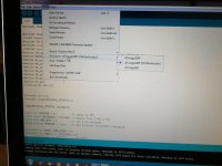
Hi I have solve problem loading "Tacho" sketch file to Arduino Nano with LCD 16x 2 12c module. The problem is "Processor selection" I was selected earlier "ATmega328P" then solved by I select ATmega328P (old Bootloader) find below screenshot. Now working perfect so Turntable Tachometer meter can work on Nano or Uno with LCD 16x2 12c module. Thanks Rajkumar
Attachments
Hi, guys
my first post here
Alexander posted a thread about this tach at lencoheaven (with link to original thread here) and i tried to build it but failed. Could you be so kind to help finding out what's wrong with my tach?
I got a Chinese Uno, installed microchip CH340G driver (instead of FT232RL), connected Uno with LCD, downloaded the last version of the script and i now i can see the "RPM ---" text at LC display. Unfortunately, i got four pins opto sensor instead of three and it's got marks A0, D0 addition to GND and VCC. I tried to connect A0 to pins 3 and 2 (A2 and A3 on Arduino Uno board) with no results. When i move my finger neaby the sensor, its diode blinks but it's not resulted on changing RPM on LCD. Any ideas how to connect a four pins sensor correctly to the Uno board? or may be some changes it the sketch file too? Thank you, guys
@andr039
I'm not familiar with the opto module you have, but my guess is that AO is an analog output and DO is a digital output. You should verify that one or both of these pins goes to ground when it senses the mark on the platter (it should stay at ground if you stop the platter in this position). Use a DC voltmeter to determine this.
This (one) output should be connected to digital input 3 on the Arduino PCB. Pin 2 on the Arduino is a test point OUTPUT and should not have anything connected to it.
Follwing your advice i connected DO to pin3 of digital inputs, got no results and unpluged the Arduino power supply. When i turned it on a while later, it has started working. Magic, practicallyThis (one) output should be connected to digital input 3 on the Arduino PCB. Pin 2 on the Arduino is a test point OUTPUT and should not have anything connected to it.
Thank you! Now i need to solder the capacitor
- Home
- Source & Line
- Analogue Source
- Digital Tachometer for record player (LCD display)